Converting a Lucas RB106 Voltage Regulator Control Box
7 posts
• Page 1 of 1
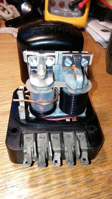
This article shows how to convert a factory RB106 voltage control box into a dummy box for use with a Dynamator, DynaLite, Dynator, etc. A fair amount has been written about using/wiring an RB106 control box for this purpose, but a step-by-step How-To Convert One hopefully will be of further help. This will work for most any negative earth car using an RB106 generator control box and dynamo-to-Dynamator, etc. conversion (see photo).
The ?D? tab is connected to the ?A? & ?A1? tabs through a fuse holder of your choice. I went with a 50A fuse. The remaining two tabs are isolated from all voltage. You are making it into just a fancy junction box. Dynamators/DynaLites, etc. are self-regulating, and don?t require cut-outs.
A used RB106 can be obtained inexpensively on eBay (e.g. US$15.00) and blends invisibly in a driver condition car, when compared to a new, more expensive dummy box. You will need an RB106, flat-blade screwdriver, wire cutters, fuse holder with 50A fuse, and one 8-32 x ?? panhead machine screw with nut and lock washer.
Step One - Remove points assemblies.
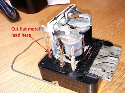
Remove cover, then the two points assemblies--one set on top of each bobbin (voltage regulator bobbin and cut-out bobbin). To do this, undo the four screws (two screws per points set) that hold them to the (thick sheet metal) frame. Cut the voltage regulator bobbin points set flat metal strip/lead that runs down the side of the box to box bottom (see photo).
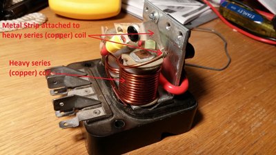
Now voltage regulator bobbin points are free. Then remove the cut-out bobbin points set, after which you will be left with the cut-out heavy series coil (the thick copper wire coil) with a strip of metal attached to it (see photo).
Step Two - Install main fuse-holder.
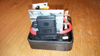
One end of fuse holder (with ring terminals) is attached to the heavy series coil metal strip with 8-32 screw & nut/lock washer, the other end of fuse holder is attached to control box frame with screw used from points-to-frame attachment. The fuse holder I had is large, so was wrapped around the frame to make it fit. Make sure it cannot chafe against any sharp corners. Wrapping it around the frame this way allows replacement of a blown fuse (when control box is mounted on the firewall) by removing the control box cover and replacing the fuse with a pair of needle-nose pliers (see photo).
Step Three - Electrically isolate remaining tabs.
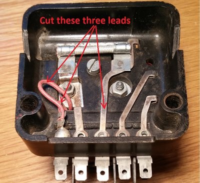
The unused control box tabs (?F? & ?E?) must be isolated from the active tabs (?D?, ?A?, & ?A1?). To do this, both of the red cloth shunt (cut-out & voltage regulator) coil/bobbin leads must be cut, as well as the flat metal strip field circuit lead. All three of these are located on the underside of the control box. Cut the two smaller red cloth wire shunt leads and the larger field circuit flat metal lead (see photo).
Confirm success with an ohmmeter?no continuity between the ?F? and ?E? tabs or any other tabs, the ?A?, ?A1?, and ?D? tabs have continuity with each other and nothing else.
Step Four - Install dummy box in car charging system.
This step assumes a negative earth Dynamator, DynaLite looks similar. Positive Earth installations require an extra relay, beyond the scope of this article. Install box in stock position in your Elan. What you have is a dummy box with ?D? tab connected to the ?A? & ?A1? tabs through the main fuse holder, remaining two tabs are dead.
Wire the Dynamator large Main Output tab to the control box ?D? tab, and the smaller Dynamator Field tab directly to one tab on the charge warning light in your tacho, or for a more authentic look, to the control box ?F? tab, then from the ?F? tab to the tacho charge warning light tab. The other tab on the tacho warning light goes to positive unfused, switched 12v white wire (on S2 Elans anyhow). The Dynamator Field tab has nothing to do with voltage regulation; it only activates the charge warning light.
Reattach the car wire(s) that were attached to the ?A? & ?A1? tabs. If there was one, you can leave ?E? tab lead on the control box or not, doesn?t matter.
It?s important to upgrade the Dynamator output-to-voltage control box and starter solenoid-to-voltage control box wires to 10-gauge, *maybe* 12-gauge (I went with 10ga.). These wires carry the heavy current of your uprated alternator when recharging battery after a start.
Step Five - Test the installation
Car run-up after installation was as expected; charge warning light glows brightly with ignition on/engine off, dimly at engine idle, extinguishes immediately when engine is revved. Charging voltage is >13.5v. The former cut-out bobbin heavy series coil now carries all the alternator output. I heavily discharged the battery (PC625) and ran the Dynamator to recharge it; the heavy series coil and metal strip didn?t warm up at all.
Comments, corrections appreciated.
Now you have a 45A charging system that is all but invisible, even to a judge .
.
The ?D? tab is connected to the ?A? & ?A1? tabs through a fuse holder of your choice. I went with a 50A fuse. The remaining two tabs are isolated from all voltage. You are making it into just a fancy junction box. Dynamators/DynaLites, etc. are self-regulating, and don?t require cut-outs.
A used RB106 can be obtained inexpensively on eBay (e.g. US$15.00) and blends invisibly in a driver condition car, when compared to a new, more expensive dummy box. You will need an RB106, flat-blade screwdriver, wire cutters, fuse holder with 50A fuse, and one 8-32 x ?? panhead machine screw with nut and lock washer.
Step One - Remove points assemblies.
Remove cover, then the two points assemblies--one set on top of each bobbin (voltage regulator bobbin and cut-out bobbin). To do this, undo the four screws (two screws per points set) that hold them to the (thick sheet metal) frame. Cut the voltage regulator bobbin points set flat metal strip/lead that runs down the side of the box to box bottom (see photo).
Now voltage regulator bobbin points are free. Then remove the cut-out bobbin points set, after which you will be left with the cut-out heavy series coil (the thick copper wire coil) with a strip of metal attached to it (see photo).
Step Two - Install main fuse-holder.
One end of fuse holder (with ring terminals) is attached to the heavy series coil metal strip with 8-32 screw & nut/lock washer, the other end of fuse holder is attached to control box frame with screw used from points-to-frame attachment. The fuse holder I had is large, so was wrapped around the frame to make it fit. Make sure it cannot chafe against any sharp corners. Wrapping it around the frame this way allows replacement of a blown fuse (when control box is mounted on the firewall) by removing the control box cover and replacing the fuse with a pair of needle-nose pliers (see photo).
Step Three - Electrically isolate remaining tabs.
The unused control box tabs (?F? & ?E?) must be isolated from the active tabs (?D?, ?A?, & ?A1?). To do this, both of the red cloth shunt (cut-out & voltage regulator) coil/bobbin leads must be cut, as well as the flat metal strip field circuit lead. All three of these are located on the underside of the control box. Cut the two smaller red cloth wire shunt leads and the larger field circuit flat metal lead (see photo).
Confirm success with an ohmmeter?no continuity between the ?F? and ?E? tabs or any other tabs, the ?A?, ?A1?, and ?D? tabs have continuity with each other and nothing else.
Step Four - Install dummy box in car charging system.
This step assumes a negative earth Dynamator, DynaLite looks similar. Positive Earth installations require an extra relay, beyond the scope of this article. Install box in stock position in your Elan. What you have is a dummy box with ?D? tab connected to the ?A? & ?A1? tabs through the main fuse holder, remaining two tabs are dead.
Wire the Dynamator large Main Output tab to the control box ?D? tab, and the smaller Dynamator Field tab directly to one tab on the charge warning light in your tacho, or for a more authentic look, to the control box ?F? tab, then from the ?F? tab to the tacho charge warning light tab. The other tab on the tacho warning light goes to positive unfused, switched 12v white wire (on S2 Elans anyhow). The Dynamator Field tab has nothing to do with voltage regulation; it only activates the charge warning light.
Reattach the car wire(s) that were attached to the ?A? & ?A1? tabs. If there was one, you can leave ?E? tab lead on the control box or not, doesn?t matter.
It?s important to upgrade the Dynamator output-to-voltage control box and starter solenoid-to-voltage control box wires to 10-gauge, *maybe* 12-gauge (I went with 10ga.). These wires carry the heavy current of your uprated alternator when recharging battery after a start.
Step Five - Test the installation
Car run-up after installation was as expected; charge warning light glows brightly with ignition on/engine off, dimly at engine idle, extinguishes immediately when engine is revved. Charging voltage is >13.5v. The former cut-out bobbin heavy series coil now carries all the alternator output. I heavily discharged the battery (PC625) and ran the Dynamator to recharge it; the heavy series coil and metal strip didn?t warm up at all.
Comments, corrections appreciated.
Now you have a 45A charging system that is all but invisible, even to a judge
Last edited by WilST on Sun Jun 25, 2017 11:04 pm, edited 1 time in total.
Pacific NorthWest USA
'Memes are not Facts'
Elan S2 26/4441 (Archivist Verified)
Panoz Esperante (an updated Elan)
550 Maranello (easy to get in trouble with that one)
Range Rover 2-Door 5-sp. (scarce in US)
'Memes are not Facts'
Elan S2 26/4441 (Archivist Verified)
Panoz Esperante (an updated Elan)
550 Maranello (easy to get in trouble with that one)
Range Rover 2-Door 5-sp. (scarce in US)
- WilST
- First Gear

- Posts: 33
- Joined: 20 Sep 2010
Thanks for this. I'm considering the upgrade from neg earth dynamo to regular alternator - I presume the instructions are the same?
Best
Steve
Best
Steve
1967 S3 SE DHC
1970 +2S (RIP - went out in a blaze of glory in 2001)
1970 +2S (RIP - went out in a blaze of glory in 2001)
-

Stevie-Heathie - Third Gear

- Posts: 276
- Joined: 08 Dec 2015
If the alternator is internally regulated, it would be similar. Depends on the alternator though. It will probably require a custom mount setup as well. I'd suggest going with a DynaLIte, Dynamator, etc. because it's simpler to mount and wire, as well as blends in much more nicely.
Stevie-Heathie wrote:Thanks for this. I'm considering the upgrade from neg earth dynamo to regular alternator - I presume the instructions are the same?
Best
Steve
Pacific NorthWest USA
'Memes are not Facts'
Elan S2 26/4441 (Archivist Verified)
Panoz Esperante (an updated Elan)
550 Maranello (easy to get in trouble with that one)
Range Rover 2-Door 5-sp. (scarce in US)
'Memes are not Facts'
Elan S2 26/4441 (Archivist Verified)
Panoz Esperante (an updated Elan)
550 Maranello (easy to get in trouble with that one)
Range Rover 2-Door 5-sp. (scarce in US)
- WilST
- First Gear

- Posts: 33
- Joined: 20 Sep 2010
This seems excessively complicated to me. In reality the Lucas control box is taken out of circuit when an alternator is fitted, but the terminals of the old control box can be used as handy connection points, without any internal butchering alterations.
This topic covered it:
lotus-electrical-f38/alternator-not-charging-t19525-15.html
And these are the two key diagrams from page 2 of that topic


Also see:
lotus-electrical-f38/nippondenso-alternator-t23679.html#p204339

This topic covered it:
lotus-electrical-f38/alternator-not-charging-t19525-15.html
And these are the two key diagrams from page 2 of that topic


Also see:
lotus-electrical-f38/nippondenso-alternator-t23679.html#p204339

Bill Williams
36/6725 S3 Coupe OGU108E Yellow over Black.
36/6725 S3 Coupe OGU108E Yellow over Black.
- billwill
- Coveted Fifth Gear

- Posts: 4417
- Joined: 19 Apr 2008
billwill wrote:This seems excessively complicated to me. In reality the Lucas control box is taken out of circuit when an alternator is fitted, but the terminals of the old control box can be used as handy connection points, without any internal butchering alterations.
I respectfully disagree, while the existing VR can be used as a connection block for the main charging circuit most of the old wiring is left hanging & is ugly. I did a similar thing to the OP on my RB340 VR... covered in http://www.lotuselan.net/forums/lotus-electrical-f38/alternator-conversion-wiring-t39043.html.
I bought a 2nd VR off eBay to modify so I have my original dyname, brackets & RB340 n case a future owner wants to revert back to original.
Phil Harrison
1972 Elan Sprint 0260K
1972 Elan Sprint 0260K
-

pharriso - Coveted Fifth Gear

- Posts: 3191
- Joined: 15 Sep 2010
Yes, using the RB106 box as-is works, but is not what I wanted, nor is the point of my article. If one wants a large fuse for the alternator that is *hidden under the cover* (which I wanted--it already saved me once), then this is the easiest way I found to do it. I did not put in extra wiring diagrams of the various ways to wire it up when done, because again that was not the goal of this article. There are many different ways to do so, depending on what generator/alternator one chooses.
A used RB106 box is a fairly common item, I have an extra one now. I tried to lay out the conversion so even those afraid of electrical stuff could do it. Maybe too many step explanations and pictures make it seem overly complicated. My intention was to lay the conversion out step-by-step as clearly as possible.
I felt the leads on the bottom of the box should be cut if using the tab(s) as handy connection points, because that will leave other unused tabs live, which I personally did not want to do. If the prospective modifier wants to put in a fuse, but doesn't mind leaving the unused tabs live, then the leads don't need to be cut. The process is then entirely reversible, no 'butchering' involved.
Pacific NorthWest USA
'Memes are not Facts'
Elan S2 26/4441 (Archivist Verified)
Panoz Esperante (an updated Elan)
550 Maranello (easy to get in trouble with that one)
Range Rover 2-Door 5-sp. (scarce in US)
'Memes are not Facts'
Elan S2 26/4441 (Archivist Verified)
Panoz Esperante (an updated Elan)
550 Maranello (easy to get in trouble with that one)
Range Rover 2-Door 5-sp. (scarce in US)
- WilST
- First Gear

- Posts: 33
- Joined: 20 Sep 2010
7 posts
• Page 1 of 1
Total Online:
Users browsing this forum: No registered users and 16 guests

