Centralising the steering rack
19 posts
• Page 1 of 2 • 1, 2
2 questions please.
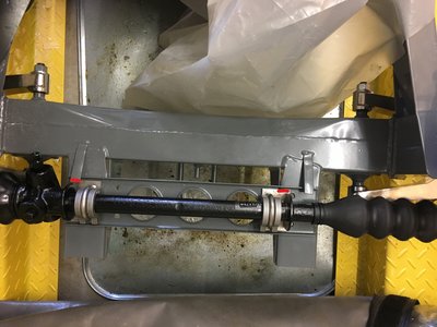
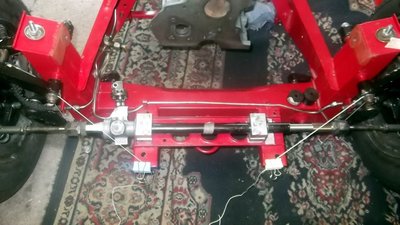
Firstly, is it true to say the rack is central if the distances shown by the red lines are equal?
Secondly, to get the track rods equal either end, do you just move it back and forth until the centre point is roughly found, or is there a peek-a-boo window like on a mini rack where you can see the mechanism is centralised left to right?
Graeme
S4 SE
S2 GTS
Caterham 420R
Sold - Peterson JPS Exige
S4 SE
S2 GTS
Caterham 420R
Sold - Peterson JPS Exige
-

661 - Coveted Fifth Gear

- Posts: 1192
- Joined: 29 Mar 2012
The position of the rack housing has no real effect on the steering geometry, the important part is the rack bar that carries the two track rods. The ball joints on each end of the bar should be the correct distance apart (not really adjustable though) but importantly should be symmetrical to the chassis centreline.
What is slightly affected by the housing being offset to one side is that there will be unequal side to side rack travel resulting in different turning circle diameters.
The original standard rubber rack mounts automatically located the rack in the position Lotus thought it should be. From memory I think that even the rigid aluminium mounts put the rack in the correct place.
Ian
68 Elan S4 DHC. Built in a weekend from a kit (just like the advert said)
-

Elanman99 - Third Gear

- Posts: 449
- Joined: 11 Sep 2003
Thanks Ian, as you can see the aluminium rack holders don't contact the rack support brackets so I've assumed an equal distance from each would be reasonable.
As you point out, it's the inner workings that are more important to get centralised.
I suspect the best way to do that is to get the hubs at the correct toe and measure the distance from the end of the track rod ends to the steering arms
As you point out, it's the inner workings that are more important to get centralised.
I suspect the best way to do that is to get the hubs at the correct toe and measure the distance from the end of the track rod ends to the steering arms
Graeme
S4 SE
S2 GTS
Caterham 420R
Sold - Peterson JPS Exige
S4 SE
S2 GTS
Caterham 420R
Sold - Peterson JPS Exige
-

661 - Coveted Fifth Gear

- Posts: 1192
- Joined: 29 Mar 2012
Elanman99 wrote:
What is slightly affected by the housing being offset to one side is that there will be unequal side to side rack travel resulting in different turning circle diameters.
Ian
Thinking of this, the rack is a simple rack and pinion so presumably if the right end goes in by and inch, the left side goes out by an inch. So as long as the wheels start of set to point in the right direction, a poorly centralised rack mechanism will merely result in the lock being reached prematurely in one direction over the other?
Graeme
S4 SE
S2 GTS
Caterham 420R
Sold - Peterson JPS Exige
S4 SE
S2 GTS
Caterham 420R
Sold - Peterson JPS Exige
-

661 - Coveted Fifth Gear

- Posts: 1192
- Joined: 29 Mar 2012
Yes but also you need to ensure that both track rods are actually the same length.
If the rack bar is offset to one side you can get perfectly correct toe in measurements in the garage, but once on the road bump steer will rear its head.
Ian
If the rack bar is offset to one side you can get perfectly correct toe in measurements in the garage, but once on the road bump steer will rear its head.
Ian
68 Elan S4 DHC. Built in a weekend from a kit (just like the advert said)
-

Elanman99 - Third Gear

- Posts: 449
- Joined: 11 Sep 2003
Elanman99 wrote:Yes but also you need to ensure that both track rods are actually the same length.
If the rack bar is offset to one side you can get perfectly correct toe in measurements in the garage, but once on the road bump steer will rear its head.
Ian
The problem has arisen because I need to cut off some of the end from both track rods to allow the track rod ends to screw on far enough to get the correct toe. This situation has come about because the TTR front disc set up requires the steering arms to be bent inwards slightly.
I think the best solution is to centralise the mechanism within the rack then centralise the rack between the two steering arms , that way the same amount of trackrod will need to be removed from each end.
I have bump steer gauge so will get around to rack height after the cutting has been undertaken.
Graeme
S4 SE
S2 GTS
Caterham 420R
Sold - Peterson JPS Exige
S4 SE
S2 GTS
Caterham 420R
Sold - Peterson JPS Exige
-

661 - Coveted Fifth Gear

- Posts: 1192
- Joined: 29 Mar 2012
Bump steer has other causes than rack height.
If I understand correctly you will end up with track rods which are shorter than the original design because the steering arm change has put the track rod end ball joint in a different position.
Seems odd to me that a brake modification can be so designed that it results in fundamental changes (even if small) to the steering geometry of the car.
Is the steering arm bending done by a specific method or just with a big hammer?
Ian
68 Elan S4 DHC. Built in a weekend from a kit (just like the advert said)
-

Elanman99 - Third Gear

- Posts: 449
- Joined: 11 Sep 2003
Rack location (within reason) should just affect maximum turn of each wheel on full lock. There is normally minimal clearance between the wheels and the anti roll bar so the rack needs to be central to avoid the wheels touching the anti-roll bar, assuming you have the right spacers in the rack to start with.
- Gray
- Second Gear

- Posts: 222
- Joined: 27 Feb 2010
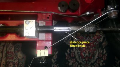
Here is how I centred the rack but it involves taking off the rack boots.
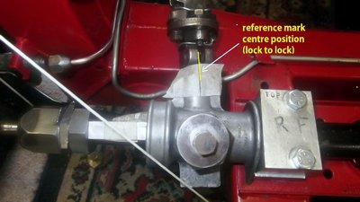
After overhauling the rack and levelling the chassis I found the central position of the rack movement (lock to lock by counting the number of turns) then halved it to get the centre position.
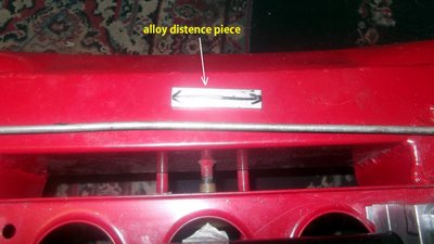
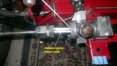
I then marked this position on the pinion to rack housing and made a reference mark, (pic 1) just to make sure I had the centre position I cut a small piece of aluminium that would just fit between the lock stop & rack housing (this fits at both ends of the rack) so the rack is now at the centre of lock to lock.(pics 2/3/4)
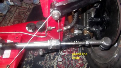
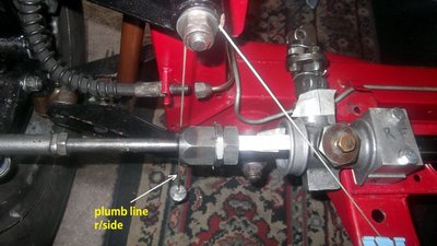
I then dropped a plumb line from the top wishbone pivots on both sides and moved the rack housing until the plumb lines were going through the tie rod pivots equally. (pics 5/6/7)
Then at ride height I set the track rod ball joints to twenty five turns on to each tie rod (as per manual basic setting) I then set the toe in adjusting both tie rods until I got the toe I required (I have W/A gauges)
The car does not have the body on yet so obviously the W/A will need to be rechecked when the body/engine etc are all fitted.
Brian
64 S2 Roadster
72 Sprint FHC
64 S2 Roadster
72 Sprint FHC
-

types26/36 - Coveted Fifth Gear

- Posts: 3402
- Joined: 11 Sep 2003
Elanman99 wrote:Bump steer has other causes than rack height.
If I understand correctly you will end up with track rods which are shorter than the original design because the steering arm change has put the track rod end ball joint in a different position.
Seems odd to me that a brake modification can be so designed that it results in fundamental changes (even if small) to the steering geometry of the car.
Is the steering arm bending done by a specific method or just with a big hammer?
Ian
The steering arms are heated up with a torch until cherry red then hit with a copper hammer. I made a metal template to ensure they were both bent equally.
Graeme
S4 SE
S2 GTS
Caterham 420R
Sold - Peterson JPS Exige
S4 SE
S2 GTS
Caterham 420R
Sold - Peterson JPS Exige
-

661 - Coveted Fifth Gear

- Posts: 1192
- Joined: 29 Mar 2012
Brian,
Thank you that's very useful. I can follow the principles in that .
Interestingly , my ball joints will only screw on 17 turns on one side and 19 on the other before they bottom out. I guess that is a different manufacturer to the original.
Thank you that's very useful. I can follow the principles in that .
Interestingly , my ball joints will only screw on 17 turns on one side and 19 on the other before they bottom out. I guess that is a different manufacturer to the original.
Graeme
S4 SE
S2 GTS
Caterham 420R
Sold - Peterson JPS Exige
S4 SE
S2 GTS
Caterham 420R
Sold - Peterson JPS Exige
-

661 - Coveted Fifth Gear

- Posts: 1192
- Joined: 29 Mar 2012
patrics wrote:Hi,
Just a point about bending the steering arms - pretty sure this is a forged part and you can not heat forged parts up and rebend them as you loose the original forged grain structure and thus loose the strength.
Regards
Steve
I thought forging was a process that involved squeezing and bending metal whilst it was hot anyway.
Ian
68 Elan S4 DHC. Built in a weekend from a kit (just like the advert said)
-

Elanman99 - Third Gear

- Posts: 449
- Joined: 11 Sep 2003
Brian,
The above is why you are always my "go to" man... EXPERT
Respect
Mark
The above is why you are always my "go to" man... EXPERT
Respect
Mark
-

mark030358 - Coveted Fifth Gear

- Posts: 1172
- Joined: 29 May 2004
19 posts
• Page 1 of 2 • 1, 2
Total Online:
Users browsing this forum: No registered users and 21 guests

