Exhaust manifold/header fit
25 posts
• Page 2 of 2 • 1, 2
steve lyle wrote:Just like on an I-beam, it's the vertical component of the beam that resists bending due to vertical loads. The horizontal components contribute very little strength in that direction. Their purpose is to prevent the vertical web from buckling horizontally.
Take a wooden board, maybe 1"x4", say 4' long. Lay it flat between two supports at the ends. Put a significant weight, say 40 lbs, on it in the middle, and watch it bend. Now take the same board, put it on edge, and the weight in the middle. Very little if any bending.
I certainly agree that you want to remove the minimum of material. There's no point to do otherwise.
Your example is valid.... However I am sorry but your wrong as to the purpose of the flanges.
The vertical web works mainly in shear, the top and bottom flanges are there primarily to contribute to the strength in bending.
The concept is all around having the maximum amount of material the maximum distance from the centre of bending, hence the flanges. Certainly a board on edge is stiffer in bending than a flat board but put flanges on the board on edge top and bottom and its much stiffer still.
Your correct that the flanges also help prevent the centre web buckling just as the centre web prevents the flanges buckling but that is not the primary purposes of the flanges or the centre web
If you have an mechanical or civil engineering engineering degree you should understand.... if you don't then I don't think I can explain it as the concepts are difficult and have to be built up in a way that's beyond what possible here.
cheers
Rohan
-

rgh0 - Coveted Fifth Gear

- Posts: 8413
- Joined: 22 Sep 2003
I have a mechanical engineering degree, fwiw. It's been awhile since, and I haven't used it much. So thank you for the refresher. You're right, of course.
So, do you think that if you put a semicircular notch in the outer edge of the flange, maybe a 1/4" deep to provide clearance to the header, that it significantly weakens the structure and needs to be compensated for with a reinforcing patch? That was really the original question.
So, do you think that if you put a semicircular notch in the outer edge of the flange, maybe a 1/4" deep to provide clearance to the header, that it significantly weakens the structure and needs to be compensated for with a reinforcing patch? That was really the original question.
Steve Lyle
1972 Elan Sprint 0248k @ https://www.mgexp.com/registry/1972-Lot ... 48K.30245/
1972 MGB Roadster @ https://www.mgexp.com/registry/1972-MG- ... 842G.4498/
2007 BMW 335i Coupe
1972 Elan Sprint 0248k @ https://www.mgexp.com/registry/1972-Lot ... 48K.30245/
1972 MGB Roadster @ https://www.mgexp.com/registry/1972-MG- ... 842G.4498/
2007 BMW 335i Coupe
-

steve lyle - Fourth Gear

- Posts: 512
- Joined: 15 Jun 2015
How do you think those of us that cold shaped the edge of the frame rail with no cut will fare? I made a former that I clamped to the under side of the frame, another on the top side, and bent and hammer formed the metal into the shape shown. Doing that actually creates an almost vertical edge parallel to the frame.
Please disregard the funny looking motor.
Please disregard the funny looking motor.
Bud
1970 +2S Fed 0053N
"Winnemucca - says it all really!!"
1970 +2S Fed 0053N
"Winnemucca - says it all really!!"
- Bud English
- Fourth Gear

- Posts: 938
- Joined: 05 Nov 2011
steve lyle wrote:I have a mechanical engineering degree, fwiw. It's been awhile since, and I haven't used it much. So thank you for the refresher. You're right, of course.
So, do you think that if you put a semicircular notch in the outer edge of the flange, maybe a 1/4" deep to provide clearance to the header, that it significantly weakens the structure and needs to be compensated for with a reinforcing patch? That was really the original question.
A localized 1/4 inch notch to clear the header will not be a problem but keep the notch smooth with no sharp transition that could cause a stress raiser and result in the flange cracking. I would make it more elliptical than semicircular.
cheers
Rohan
-

rgh0 - Coveted Fifth Gear

- Posts: 8413
- Joined: 22 Sep 2003
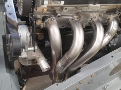
Update ..I have sorted it.... 
As discussed earlier in the thread I really didn't want to notch the chassis and modifying the No3 pipe would have been a diffult task meaning either cylinder head or engine removal.
So just to update on how I have hopefully sorted the problem....
I disconnected the engine mounts and with the engine balanced on a jack I assessed that if I could move the engine over by 3/16th of an inch it would give me sufficient clearance between the No3 downpipe and the chassis. However, elongating the holes in the left mount by 3/16th I thought was just too much and would have not left much metal on the outside of the mount and left a weak area.
So I had a friend with a lathe make me up some spacers 3/16th of an inch longer than the standard original ones which when fitted with appropriately longer bolts pushed the engine over slightly. I then elongated the right engine mount holes horizontally as required to get the bolts in on that side.
Pig of a job though!
I now have clearance....Not a lot ...but but I think it is now ok. In reality it is more than shown due to the angle of the photo. There is always the chance I suppose that moving the engine over will affect the drivetrain. i.e. the prop, but I will cross that bridge if/when it does.
Alan.
Alan
Currently:-
1971 +2 S130/ 5speed Type 9.
1960 MGA 1600 Mk1 Coupe. 5speed type 9.
Currently:-
1971 +2 S130/ 5speed Type 9.
1960 MGA 1600 Mk1 Coupe. 5speed type 9.
- alanr
- Coveted Fifth Gear

- Posts: 1055
- Joined: 14 Sep 2018
That looks great. That's plenty of clearance. There should be absolutely no issue over the propshaft alignment, the U-joints can easily take up a tiny bit more angle.
Regards,
Dan Wise
Regards,
Dan Wise
There is no cure for Lotus, only treatment.
-

StressCraxx - Coveted Fifth Gear

- Posts: 1289
- Joined: 26 Sep 2003
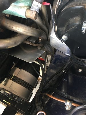
Should be fine, mine has similar clearance and hasn?t been any problem, you can see in the picture that I have added a shield to stop the alternator getting fried as I had several fail previously and I also have added some heat shield on the area of the footwell adjacent to the manifold as the original paint was a bit blistered there.
Change is inevitable, except from a vending machine!
- Bigbaldybloke
- Fourth Gear

- Posts: 889
- Joined: 16 May 2017
BBB..Thanks for the reassurance..
Yes I think I too need now to sort a heatshield for the alternator. I am also concerned about heat affecting the engine mount so I was thinking of making some sort of heatshield to protect both.
What have you used on the footwell area...Zircotec self adhesive?
Yes I think I too need now to sort a heatshield for the alternator. I am also concerned about heat affecting the engine mount so I was thinking of making some sort of heatshield to protect both.
What have you used on the footwell area...Zircotec self adhesive?
Alan
Currently:-
1971 +2 S130/ 5speed Type 9.
1960 MGA 1600 Mk1 Coupe. 5speed type 9.
Currently:-
1971 +2 S130/ 5speed Type 9.
1960 MGA 1600 Mk1 Coupe. 5speed type 9.
- alanr
- Coveted Fifth Gear

- Posts: 1055
- Joined: 14 Sep 2018
Yes it was zircotec self adhesive, it?s on the vertical face and the areas you can see. If you look closely at the photo you can see I?ve also put some on the top and rear sides of the engine mount, as I had the same concerns as you.
Change is inevitable, except from a vending machine!
- Bigbaldybloke
- Fourth Gear

- Posts: 889
- Joined: 16 May 2017
25 posts
• Page 2 of 2 • 1, 2
Total Online:
Users browsing this forum: No registered users and 22 guests


