pulley/chassis clearance and some rebuild photos
5 posts
• Page 1 of 1
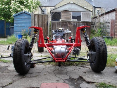
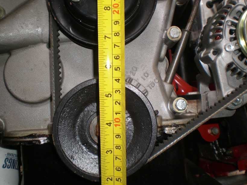
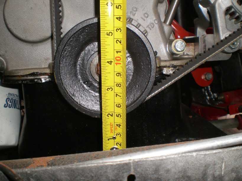
Would someone with a Spyder chassis be able to measure the clearance between the bottom of the crankshaft pulley and the top of the vacuum tank please? Engine is looking a bit high, but just wanted to check! Thanks in advance.
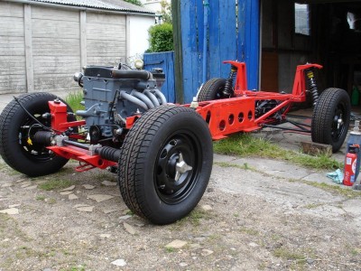
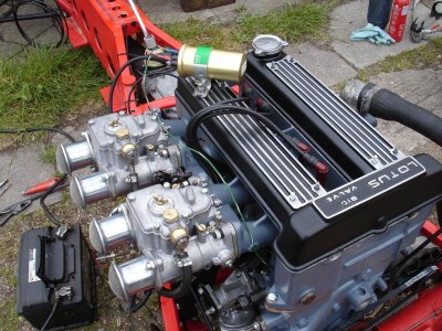
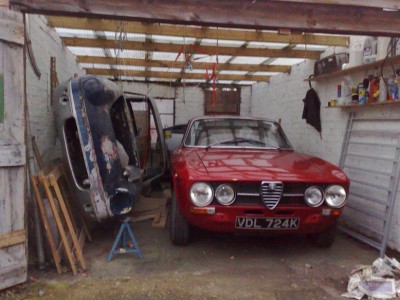
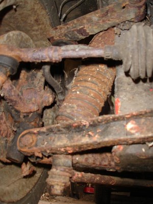
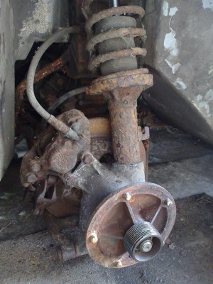
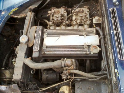
...and some photos of things so far (and some 'before' pics too.) Fired up the engine yesterday, started first time but with no radiator (and no back box!) I didn't run it for more than a couple of seconds. Very satisfying, especially after doing it all myself (except rebuilding the gearbox, and putting the tyres on the rims...) A couple more jobs to do then on to the bodywork. If you look closely you should be able to spot the odd bit to paint, gaskets, nuts etc.
fantastic forum - 99% of info I've needed so far has been on here or in Buckland.
will
- ill_will
- Third Gear

- Posts: 277
- Joined: 18 Apr 2008
if you are at or around 1 3/4 inches you should be good.


-

garyeanderson - Coveted Fifth Gear

- Posts: 2626
- Joined: 12 Sep 2003
Will,
Fantastic pictures! When you look at the before photos, it's hard to believe it's the same car. It looked like a complete write off. Are you planning on using an electric water pump? I noticed you have the water pump plugged off and the fan belt now operates the alternator only. It also looks like you removed the original impeller. I like the look of the spark plug wires. What brand are they and where did you get them? Finally, are you planning on incorporating a center power bulge to accomodate the coil?
Fantastic pictures! When you look at the before photos, it's hard to believe it's the same car. It looked like a complete write off. Are you planning on using an electric water pump? I noticed you have the water pump plugged off and the fan belt now operates the alternator only. It also looks like you removed the original impeller. I like the look of the spark plug wires. What brand are they and where did you get them? Finally, are you planning on incorporating a center power bulge to accomodate the coil?
Frank Howard
'71 S4 SE
Minnesota
'71 S4 SE
Minnesota
- Frank Howard
- Fourth Gear

- Posts: 919
- Joined: 30 Mar 2004
Gary - thanks for those measurements, I'll take a look. From memory that sounds roughly what it is... fingers crossed.
Frank - yeah, I'm planning on running the Davies Craig EWP 80 with digital controller. Expensive, but with definite benefits. To my engineer's mind it seems like an elegant solution that avoids the idle vs high rpm compromise necessary with mechanical pumps. When I took the engine to pieces, the alloy ring that is contoured to fit the impeller was firmly corroded into the back part of the timing chest. It wasn't coming off (eventually took almost a ton on the hydraulic press to separate it.) What then followed was trying to take the whole timing chest off as one piece: firstly, undoing the bolt which holds it to the block was a nightmare, as was unfolding the two tab washes that hold the jackshaft thrust plate in place and removing those bolts. Then the whole timing chest and jackshaft assembly could be removed as one, before angle grinding off the water pump impeller to allow the two halves to be separated... not a great design.
I turned up an aluminium alloy bung with a lip on and lightly pressed it in in place of the water pump bearing. The circular contoured alloy ring (with notch) went back in too, with silicon. I also went down the Buckland route of using three hand cut gaskets between the two halves of the timing case. For the record the new fan belt length was 650 mm but I haven't dug out the alt. bracket yet from the numerous boxes of bits in the attic so can't confirm that it will work for definite. It looks about right though.
The plug leads and caps are NGK ones - I got them from Susan Miller. They have nice NGK lettering on the other side in white. They are slightly wierd in that they require the little screw-on bits at the top of the spark plugs to be removed, just leaving a threaded end, which they then press over. The connection seems positive though. I haven't seen this style before.
The plan is to mount the servo, washer bottle and oil catch tank on top of the cam cover too to fully justify the power bulge...
will
- ill_will
- Third Gear

- Posts: 277
- Joined: 18 Apr 2008
I love pictures like that - looks great Will.
I had those NGK leads on my previous Plus 2, I remember they had a nice positive feel as they were pushed on to the plugs. I had forgotten about them, wish I'd remembered before I bought a new, normal, set from Paul Matty.
Good luck with the rest of the rebuild
I had those NGK leads on my previous Plus 2, I remember they had a nice positive feel as they were pushed on to the plugs. I had forgotten about them, wish I'd remembered before I bought a new, normal, set from Paul Matty.
Good luck with the rest of the rebuild
-

Robbie693 - Coveted Fifth Gear

- Posts: 1514
- Joined: 08 Oct 2003
5 posts
• Page 1 of 1
Total Online:
Users browsing this forum: No registered users and 25 guests

