
Spring Compressor Front Plus 2
19 posts
• Page 1 of 2 • 1, 2
![]() Post by: cal44 » Sun May 12, 2013 9:46 pm
Post by: cal44 » Sun May 12, 2013 9:46 pm
I am making my own spring compressor. I always over build so I am using two pieces of 1/2" plate 6" X 6", threaded 5/8" rod and some mild steel pipe pup to weld on for safety.
Here is what I don't get. The descriptions and pictures of other compressors on this site write about a 2 1/2" hole on one plate and the plate, one guy states 2 1/4 and another I think was 1.75.
The spring keeper on the AVO shock is the same outside diameter as the spring. So, if I compress the spring (top) how do I get the keeper on the spring?.........the plate is holding the spring down.
Did this make sense? I am sure there is a simple explanation for the question but I just cannot rap my feeble mind around it...............
All opinions will be helpful, pictures even better............I'm a picture guy.
Regards,
mike
"Be Polite, Be Professional, But have a plan to kill everyone you meet"
General "Mad Dog" James Mattis United States Marines
General "Mad Dog" James Mattis United States Marines
- cal44
- Third Gear

- Posts: 498
- Joined: 28 Nov 2010
![]() Post by: billwill » Sun May 12, 2013 10:52 pm
Post by: billwill » Sun May 12, 2013 10:52 pm
Is this spring compressor for the rear suspension springs?
I found these pictures on the web, which shows the usual type in use. As you see they operate only on the spring itself, an not on any plates that hold the ends.


I found these pictures on the web, which shows the usual type in use. As you see they operate only on the spring itself, an not on any plates that hold the ends.
Bill Williams
36/6725 S3 Coupe OGU108E Yellow over Black.
36/6725 S3 Coupe OGU108E Yellow over Black.
- billwill
- Coveted Fifth Gear

- Posts: 4417
- Joined: 19 Apr 2008
![]() Post by: robertverhey » Sun May 12, 2013 10:55 pm
Post by: robertverhey » Sun May 12, 2013 10:55 pm
Hmm post title says front....
Seen this? Page 3
lotus-elan-f19/australia-now-has-one-more-elan-t21042-30.html
Seen this? Page 3
lotus-elan-f19/australia-now-has-one-more-elan-t21042-30.html
- robertverhey
- Fourth Gear

- Posts: 695
- Joined: 20 Feb 2007
![]() Post by: billwill » Sun May 12, 2013 11:14 pm
Post by: billwill » Sun May 12, 2013 11:14 pm
Ah, I've not disassembled a front shocker+spring unit, but I think you make a big enough hole in the top of the compressor, so that after you have compressed the spring, you can undo the end fittings & nut or collets on the damper shaft.
Then you unwind the spring compressor slowly and the cap moves past it original position and off the shaft, keep unwinding until all spring tension is released and then you can disassemble the unit.
http://www.rdent.com/manuals/plus2/fron ... ion/ca.htm
But I'm not sure.
Then you unwind the spring compressor slowly and the cap moves past it original position and off the shaft, keep unwinding until all spring tension is released and then you can disassemble the unit.
http://www.rdent.com/manuals/plus2/fron ... ion/ca.htm
But I'm not sure.
Bill Williams
36/6725 S3 Coupe OGU108E Yellow over Black.
36/6725 S3 Coupe OGU108E Yellow over Black.
- billwill
- Coveted Fifth Gear
- Posts: 4417
- Joined: 19 Apr 2008
![]() Post by: Bud English » Mon May 13, 2013 6:32 pm
Post by: Bud English » Mon May 13, 2013 6:32 pm
Mike, I had a look at the AVO site and I can see your dilemma. Your shocks don't come apart like the stock ones or Koni's. The spring retainer is the same diameter as the spring, but then you said that in your original post. It looks to me like you are locked into a compressor that grabs the spring. My compressor that worked that way on my rear struts was way too big to work on the fronts. You may have to contact AVO to see what they recommend. Their site didn't list a compressor in their tool section.
Just as a side note, you may want to look at the posts concerning the lack of support from AVO and unavailability of parts for their "rebuildable" shocks. I've had no experience with them. I'm only going on what came up in my search about them.
Just as a side note, you may want to look at the posts concerning the lack of support from AVO and unavailability of parts for their "rebuildable" shocks. I've had no experience with them. I'm only going on what came up in my search about them.
Bud
1970 +2S Fed 0053N
"Winnemucca - says it all really!!"
1970 +2S Fed 0053N
"Winnemucca - says it all really!!"
- Bud English
- Fourth Gear
- Posts: 942
- Joined: 05 Nov 2011
![]() Post by: cal44 » Mon May 13, 2013 9:37 pm
Post by: cal44 » Mon May 13, 2013 9:37 pm
Bud,
This is what Dave Bean carries. Funny thing is I read the same thing about Spax...........oh' my head cuz they ain't cheap.
We will see if they last..........if not?, gawd help em' cuz this big mouth cowboy will tell everyone.
As for attaching the keeper on the spring I am hoping someone else has had to do this so the I may get a few tips.
The guy at Bean suggested I take them to a bike shop. Also I was thinking about compressing the spring and securing it in a compressed position with underground pulling ribbon. It is the material the underground electric guys use to pull cable in duct. Maybe looping it four times on each side.
I will take some pix to share with the others in case my explanation doesn't make sense.
mike
"Be Polite, Be Professional, But have a plan to kill everyone you meet"
General "Mad Dog" James Mattis United States Marines
General "Mad Dog" James Mattis United States Marines
- cal44
- Third Gear
- Posts: 498
- Joined: 28 Nov 2010
![]() Post by: Bud English » Mon May 13, 2013 10:18 pm
Post by: Bud English » Mon May 13, 2013 10:18 pm
Hey, that sounds like it will work. Compress them, tie off the spring and release the compressor. I might be tempted to leave the compressor in place after loosening for a bit to test the resolve of the "pulling ribbon.
If that works, you could probably remove the spring, put a piece of pipe through it and place it back in the compressor to release the compression on the spring, if needed. The pipe being a little safety insurance.
If that works, you could probably remove the spring, put a piece of pipe through it and place it back in the compressor to release the compression on the spring, if needed. The pipe being a little safety insurance.
Bud
1970 +2S Fed 0053N
"Winnemucca - says it all really!!"
1970 +2S Fed 0053N
"Winnemucca - says it all really!!"
- Bud English
- Fourth Gear
- Posts: 942
- Joined: 05 Nov 2011

![]() Post by: cal44 » Thu May 23, 2013 9:02 pm
Post by: cal44 » Thu May 23, 2013 9:02 pm
I have now gone to Spax with the coil adjustment. I have spent six hours trying to install the shock into the spring. The Spax has the same setup (collet/keeper). I get the spring squeezed no problem between two plates but have yet to find something with will hold the spring tight until I can insert the shock and lock it in.
The flat rope didn't work, tie wraps (10) all broke when I let the pressure off the spring...........
This all very frustrating, but, I know there is an answer on how to do it, I just haven't figured it out.
I can't stand depending on a shop to do this. Guys for decades have done this at home..........what the heck am I missing? The spring squeezes flat so that isn't the problem. The flat rope, rated at 250 lbs. stretches to much.
I don't want to screw up the powder coating on springs
mike
"Be Polite, Be Professional, But have a plan to kill everyone you meet"
General "Mad Dog" James Mattis United States Marines
General "Mad Dog" James Mattis United States Marines
- cal44
- Third Gear
- Posts: 498
- Joined: 28 Nov 2010
![]() Post by: robertverhey » Thu May 23, 2013 10:07 pm
Post by: robertverhey » Thu May 23, 2013 10:07 pm
I'm trying hard to visualise this, and I'm not sure how the top plate / collet is held in place on the assembled unit, if not by a threaded arrangement on collet/shaft. But if I'm reading your posts right, you are compressing the spring independently, and then trying to put the shock in?
Just thinking laterally, would it be better to compress the spring while on the shock, but leaving the top of the spring exposed, ie rig something up that grabs onto the second or third coil from the top?
Just thinking laterally, would it be better to compress the spring while on the shock, but leaving the top of the spring exposed, ie rig something up that grabs onto the second or third coil from the top?
- robertverhey
- Fourth Gear
- Posts: 695
- Joined: 20 Feb 2007
![]() Post by: cal44 » Thu May 23, 2013 10:55 pm
Post by: cal44 » Thu May 23, 2013 10:55 pm
 Yep, I tried that as well, having the shock inside the spring and then compressing the spring. I failed to write that, sorry. The problem it the collet is the same diameter as the spring.
I was also thinking about going down a coil and coming up with something to compress it. I'll take some pictures and post. I know darn will I cannot be the only one that runs into this.
mike


"Be Polite, Be Professional, But have a plan to kill everyone you meet"
General "Mad Dog" James Mattis United States Marines
General "Mad Dog" James Mattis United States Marines
- cal44
- Third Gear
- Posts: 498
- Joined: 28 Nov 2010
![]() Post by: billwill » Fri May 24, 2013 12:49 am
Post by: billwill » Fri May 24, 2013 12:49 am
The manufacturers AVO advertize them as rebuildable, so why don't you phone them up and ask how to do it?
~~~~~~~~
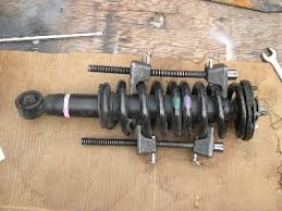
From your photos it is pretty clear that you have to compress the spring with the shock absorvber in place, then pull the centre rod out to its full extent (if it has not already done that from internal pressure), then slip the collet on and unscrew the nuts so that the collet takes the pressure.
So the problem becomes, how do you get the top of the spring compressor out after you have released the compression?
One method might be to make that compressor top plate much thicker and split it across into two identical halves. Then drill holes through the sides of the top plate right through both and use threaded rod or bolts to clamp the two pieces together into your original configuration.
This is a posh professional version of such an adaptor:

Then after you have performed the compression and collet insertion and tension release, remove the long compression rods and unbolt the two halves of the top plate and work the halves out from between the top of the spring and bottom of the collet. It will be difficult I expect and they may fly across the room.
~~~~~~~~~~
An alternative to the two-piece top plate might be to just make an entry slot in the side akin to the slot in that collect, but wider, with a width equal to that diameter of that bottom section of the collect. Make sure it will slide on and off the collet sideways before putting it under pressure. Grease it maybe.
A bit like these, but with holes for your compression screw rods.

Then as above, after you have performed the compression and collet insertion and tension release, remove the long compression rods and tap the top plate sideways out from between the collet and spring... With care.
NOTE: it would be safer for this version to remake it as a THREE-rod compressor with the threaded rods in a triangle formation, because the slotted top is less stable than your current two-rod closed top version.
~~~~~~~~
From your photos it is pretty clear that you have to compress the spring with the shock absorvber in place, then pull the centre rod out to its full extent (if it has not already done that from internal pressure), then slip the collet on and unscrew the nuts so that the collet takes the pressure.
So the problem becomes, how do you get the top of the spring compressor out after you have released the compression?
One method might be to make that compressor top plate much thicker and split it across into two identical halves. Then drill holes through the sides of the top plate right through both and use threaded rod or bolts to clamp the two pieces together into your original configuration.
This is a posh professional version of such an adaptor:
Then after you have performed the compression and collet insertion and tension release, remove the long compression rods and unbolt the two halves of the top plate and work the halves out from between the top of the spring and bottom of the collet. It will be difficult I expect and they may fly across the room.
~~~~~~~~~~
An alternative to the two-piece top plate might be to just make an entry slot in the side akin to the slot in that collect, but wider, with a width equal to that diameter of that bottom section of the collect. Make sure it will slide on and off the collet sideways before putting it under pressure. Grease it maybe.
A bit like these, but with holes for your compression screw rods.
Then as above, after you have performed the compression and collet insertion and tension release, remove the long compression rods and tap the top plate sideways out from between the collet and spring... With care.
NOTE: it would be safer for this version to remake it as a THREE-rod compressor with the threaded rods in a triangle formation, because the slotted top is less stable than your current two-rod closed top version.
Last edited by billwill on Fri May 24, 2013 1:35 am, edited 3 times in total.
Bill Williams
36/6725 S3 Coupe OGU108E Yellow over Black.
36/6725 S3 Coupe OGU108E Yellow over Black.
- billwill
- Coveted Fifth Gear
- Posts: 4417
- Joined: 19 Apr 2008
![]() Post by: billwill » Fri May 24, 2013 12:58 am
Post by: billwill » Fri May 24, 2013 12:58 am
Why is that HEX area there below the collet retainer disk?
Is it there so that you can hold it with a spanner while you unscrew all the rest of the bits off the top of the shaft. If so it is easy. Compress the spring including the collet over the naked shaft. Go far enough down so that you can get a spanner onto that hex. Place the collet retaining disk on and the other threaded bits, do them up tight taking the torque on that spanner, fit any securing split pins or whatever, then release the spring compressor.
Is it there so that you can hold it with a spanner while you unscrew all the rest of the bits off the top of the shaft. If so it is easy. Compress the spring including the collet over the naked shaft. Go far enough down so that you can get a spanner onto that hex. Place the collet retaining disk on and the other threaded bits, do them up tight taking the torque on that spanner, fit any securing split pins or whatever, then release the spring compressor.
Bill Williams
36/6725 S3 Coupe OGU108E Yellow over Black.
36/6725 S3 Coupe OGU108E Yellow over Black.
- billwill
- Coveted Fifth Gear
- Posts: 4417
- Joined: 19 Apr 2008
![]() Post by: robertverhey » Fri May 24, 2013 1:42 am
Post by: robertverhey » Fri May 24, 2013 1:42 am
Forgive me if I'm being thick, but I'm still struggling to understand the problem. The pics help explain how the top is constructed. Question: does the shiny metal thick washer screw onto the shaft? If so it's same setup as mine. So why not compress on the larger black slotted collet and when sufficiently compressed unscrew the smaller metal washer referred to above? Then gradually release the spring / damper until the dangerous compression is released.... The shock will keep it all straight until it's loose.
Much the same as I did....
Or am I missing something?
Much the same as I did....
Or am I missing something?
- robertverhey
- Fourth Gear
- Posts: 695
- Joined: 20 Feb 2007
![]() Post by: Chancer » Fri May 24, 2013 11:25 am
Post by: Chancer » Fri May 24, 2013 11:25 am
I have been using ratchet strraps to compress springs for coil-over shocks for decades, its by far the simplest solution, use a pair and gradually tighten each one so that the spring does not distort.
Alternatively if you have a decent drill press with spindle height locking then you can compress the spring or the spring/damper assembly on that and then just thread the straps through and secure them, likewise when refitting, take the strain off the spring in the drill press, remove or loosen the ratchet straps then release the pressure progressively.
Not sure if it would work with one of the toy chinese 500 watt drill presses, they probably dont have the throat depth.
- Chancer
- Coveted Fifth Gear
- Posts: 1133
- Joined: 20 Mar 2012
19 posts
• Page 1 of 2 • 1, 2
Total Online:
Users browsing this forum: No registered users and 51 guests