Oversteer on corners
Chancer wrote: total toe out being 32 minutes and the thrust angle of 18 minutes (surely that should be 16 minutes?) means the car will be crabbing does it not?
the maths are not wrong in the system : (34 -(-04))/2=19' after for (34-(-02))/2=18' before
Regarding the trust angle more specifically, if the car is straight and behaving well in general, this may raise the question of the car being aligned correctly on the bench.
The issue of properly using the system has already been raised earlier, and the suggestion to get an other check somewhere else rightfully made... esp. before taking any drastic corrective step.
S4SE 36/8198
-

nmauduit - Coveted Fifth Gear

- Posts: 1998
- Joined: 02 Sep 2013
I think that the Hunter system takes rolling readings to compensate for the car not being exactly parallel to the measurement line when calculating thrust.
But again a lot does depend on the level of technician understanding to get a satisfactory result.
In Jon's case alarm bells should have rung when changes to settings that hadn't been altered turned up.
But again a lot does depend on the level of technician understanding to get a satisfactory result.
In Jon's case alarm bells should have rung when changes to settings that hadn't been altered turned up.
- MarkDa
- Coveted Fifth Gear

- Posts: 1116
- Joined: 15 Apr 2017
Hi Jon
You could try one of these as long as you have a level surface:
https://www.youtube.com/watch?v=X0ytDJ0mJoQ
https://www.ebay.co.uk/p/Gunson-G4008-T ... 2255356490
Regards
John
You could try one of these as long as you have a level surface:
https://www.youtube.com/watch?v=X0ytDJ0mJoQ
https://www.ebay.co.uk/p/Gunson-G4008-T ... 2255356490
Regards
John
-

c42 - Third Gear

- Posts: 312
- Joined: 10 Sep 2009
A cheap way to check toe is to make a couple of square plates out of plywood, chip board, or aluminum plate close to the overall diameter of the tire. Cut slots at the front and rear of the plates about 1" above the floor, with the plates placed firmly against the tires. Use a pair of tape measures, hooking the ends in the slots on one board and the length of the tape through the slots of the opposite board. A quick check of the measurements should show a difference between the front and rear tapes where they exit the plates. If the measurement on the front tape is less than the rear tape, you have toe in. Half the distance between the front and rear measurements will give you the amount of toe. Easy to package and stow and a quick check can be done in a couple of minutes.
Rob Walker
26-4889
50-0315N
1964 Sabra GT
1964 Elva Mk4T Coupe (awaiting restoration)
1965 Ford Falcon Ranchero, 302,AOD,9",rack and pinion,disc,etc,etc,etc
1954 Nash Healey LeMans Coupe
Owning a Lotus will get you off the couch
26-4889
50-0315N
1964 Sabra GT
1964 Elva Mk4T Coupe (awaiting restoration)
1965 Ford Falcon Ranchero, 302,AOD,9",rack and pinion,disc,etc,etc,etc
1954 Nash Healey LeMans Coupe
Owning a Lotus will get you off the couch
- prezoom
- Coveted Fifth Gear

- Posts: 1176
- Joined: 16 Mar 2009
Been there, done that... sort of..
lotus-suspension-f42/take-the-old-geezer-method-for-steering-alignment-t40991.html
I wasn't sure I'd managed to set it up accurately, though, and I wanted to see what the rear toe in was. Using a stick with pointers on it only gives total toe in, not per side toe in.
lotus-suspension-f42/take-the-old-geezer-method-for-steering-alignment-t40991.html
I wasn't sure I'd managed to set it up accurately, though, and I wanted to see what the rear toe in was. Using a stick with pointers on it only gives total toe in, not per side toe in.
-

JonB - Coveted Fifth Gear

- Posts: 2357
- Joined: 14 Nov 2017
Chancer wrote: ........even at 250% magnification my eyes struggle to read the figures, I was sure it was the RH rear that was toeing out but now it looks to be the left, isnt it 34 minutes of toe out and not 2 minutes?
My eyes are struggling too, but if I'm seeing it correctly, just concentrating on the 'toe' measurements, before adjustments, R/H/Front was 0 degrees 48 minutes, L/H/Front was 0 degrees 42 minutes, R/H/Rear was ? 0 degrees 04 minutes, & L/H/Rear was 0 degrees 34 minutes. After adjustment, we have R/H/Front 0 degrees 13 minutes, L/H/Front 0 degrees 13 minutes, R/H/Rear ? 0 degrees 02 minutes & L/H/Rear 0 degrees 34 minutes. As the R/H/Rear figures are the only ones with a ? in front, I'm taking those to be Negative toe, or toe out & all the others to be positive toe, or toe in. If I have that right, all wheels are toeing in except the R/H/Rear, which is toeing out by a tiny amount. The L/H/Rear is the only figure to remain unchanged, but the difference of 02 minutes between the before & after on the R/H/Rear could easily be a tiny discrepancy in the wheel rim.
I still think, if the figures are to be believed, that the lack of caster angle up front would be the main cause of vague steering. First step for me would be to confirm if those figures are correct, & if they are, try to figure out why.
Regards, Tim
- Orsom Weels
- Third Gear

- Posts: 409
- Joined: 31 Oct 2011
Thats a relief, my first reading was the correct one, I have to wear different glasses according to how my eyes are at a particular time.
So a small amount of toe out on one rear and 34' toe in on the other giving a crab (thrust angle) of 18'.
What should the rear toe in be? and is it total or per side.
Agree with your comments regarding castor, I think there are 2 seperate issues, instability and oversteer, 2 causes and you have correctly identified both.
- Chancer
- Coveted Fifth Gear

- Posts: 1133
- Joined: 20 Mar 2012
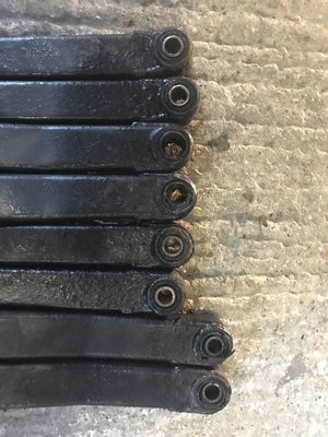
..also, it looks like the lower O/S spindle is bent backwards a little bit. Must have been curbed.
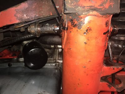
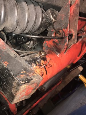
However, the problem I have now is that the spindle itself is seized into the chassis, rusted solid. I had to cut one end off as the bush inners are seized too. I think I will have to leave it soaking in WD40. The problem now is that the inner tube that the spindle goes through is welded to the front cross member and as such not accessible for application of heat / cold.
I have tried fitting washers and a nut to one end and torquing it right up so as to draw the spindle out, but it is not budging. There's also a seized inner bush sleeve attached on that side and this might be causing problems,
What can I do?
-

JonB - Coveted Fifth Gear

- Posts: 2357
- Joined: 14 Nov 2017
Cut off the stub nearly level with the boss but leave proud by 2 - 3mm, centre punch the centre, then drill a pilot hole to ensure you have the centre, then gradually increase drill size to reduce the remaining spindle until the remaining wall thicknes is minimal. If it still does not move punch the remaining 2 - 3 mm in towards centre then apply liberal dose of Plus Gas to both side. Leave overnight then try again.
Elan +2
Elise mk 1
Elise mk 1
- Donels
- Fourth Gear

- Posts: 709
- Joined: 10 Sep 2016
Well, I had a chat with Spyder and they say I should use releasing agent like Plus Gas and heat. Patience, too. If all else fails, they can redo the joint with a jig they have without taking the body off. Expensive, I expect; plus I will have to get it there somehow. But at least I will not need to remove the body, so there's some ray of hope.
Meanwhile I have ordered a new spindle and the new bushes are being pressed into the arms.
Fingers crossed!
Meanwhile I have ordered a new spindle and the new bushes are being pressed into the arms.
Fingers crossed!
-

JonB - Coveted Fifth Gear

- Posts: 2357
- Joined: 14 Nov 2017
JonB wrote:..also, it looks like the lower O/S spindle is bent backwards a little bit. Must have been curbed.
However, the problem I have now is that the spindle itself is seized into the chassis, rusted solid. I had to cut one end off as the bush inners are seized too. I think I will have to leave it soaking in WD40. The problem now is that the inner tube that the spindle goes through is welded to the front cross member and as such not accessible for application of heat / cold.
I imagine you initially thought of replacing the spindles (replaceable spindles being a specifics of Spyder frames - actually they even erroneously sent me a pair at some point)
Applying the usual heat/cold/~wd40/hammer may not be practical, so do you have access for drilling through (starting with a small diameter, and a lot of patience) ?
__ well a number similar suggestions of drilling already made while I was typing ... good luck !
Last edited by nmauduit on Wed Feb 14, 2018 3:28 pm, edited 1 time in total.
S4SE 36/8198
-

nmauduit - Coveted Fifth Gear

- Posts: 1998
- Joined: 02 Sep 2013
Total Online:
Users browsing this forum: No registered users and 4 guests


