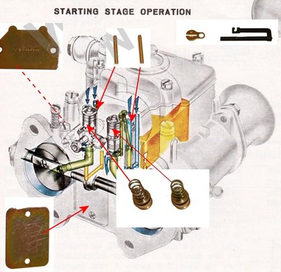
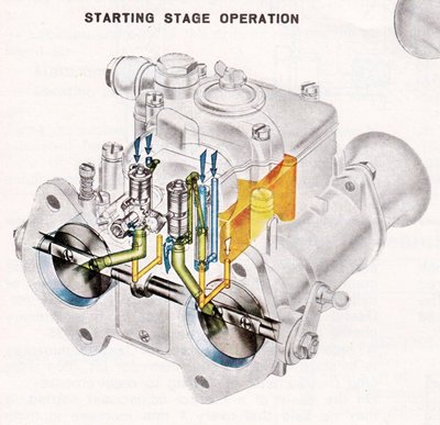
Weber Cold Start Elimination
30 posts
• Page 2 of 2 • 1, 2
Hi Simon.
We were also looking at blanking kits and came up with the same question...
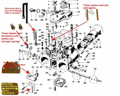
"There is also a replacement accelerator pump actuator arm. Why? I don't know but maybe it'll become obvious as to what part the accelerator arm plays in the choke circuit."
If you do find that it is of importance to fit this for some reason, let us know. We are thinking it might just be supplied as Weber's experience is that its often found worn when doing the "Blanking" task.
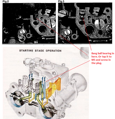
(PS.... The "Parts" diagram below is actually a DCOE45, but the Cold-Start part of the carb is the same I believe)
John "Freddie" Nelson, Berks UK
26/5592 - Rebuilding
S4-Sprint DHC - Now at a new home.....
26/5592 - Rebuilding
S4-Sprint DHC - Now at a new home.....
- Fredtech
- Second Gear

- Posts: 68
- Joined: 19 Oct 2010
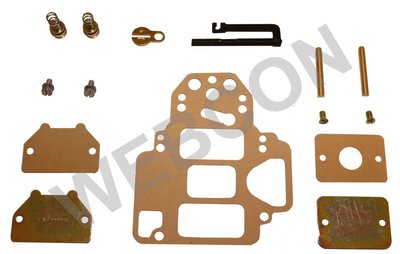
What's more John the Webcon picture you inserted misses a couple of items that their kit includes!
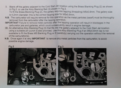
There are two blanking plug with an M5 thread and two ball bearings
You have to choose which of these to use!
They are for the airway that is just beside the cold start jet.
Either tap a thread, remove all swarf and screw in the plug
Or bang the ball bearing into it with a hammer. Yes really!


This poor scan of the kits accompanying notes shows the fitment of the threaded blank fig 2 and the alternative ball bearing technique fig 3.
There are two blanking plug with an M5 thread and two ball bearings
You have to choose which of these to use!
They are for the airway that is just beside the cold start jet.
Either tap a thread, remove all swarf and screw in the plug
Or bang the ball bearing into it with a hammer. Yes really!
This poor scan of the kits accompanying notes shows the fitment of the threaded blank fig 2 and the alternative ball bearing technique fig 3.
Simon
'67 S3 FHC 36/7002
'69 +2 50/1370 (stolen '00)
'67 S3 FHC 36/7002
'69 +2 50/1370 (stolen '00)
-

simonknee - Third Gear

- Posts: 392
- Joined: 18 Sep 2003
I found the post that billwill was on about - regarding why there are holes in the throttle inspection plate.
lotus-carbs-f40/webers-leaking-ring-mounts-t30334.html
It's actually a 2014 thread that got resurrected recently - as these things do.
Check out the post by fatboyoz. He says the holes are to prevent a vacuum forming inside this area. He goes on to say that when such a vacuum is created the fuel can be drawn in from surprising locations... including... the accelerator pump rod!
So maybe the reason they are including a new pump rod is to reduce this possibility since:
1. A fuel weep from the inspection cover could be mistaken from a cold start weep and the punter has just bought a kit to cure leaks!
2. They include a no-hole inspection cover in the kit and fresh gaskets so the possibility of a vacuum in this region is increased.
Fortunately this is making the kit look better value since I do get an occasional weep from the inspection cover too. (This is definitely in addition to a weep from the cold start covers) Plus now I have two sets of inspection covers so I can drill a hole in one pair and see which is less weepy!
I also found a google scan of book that covers a simpler method of blanking what they delightfully refer to as "discharge holes"
https://books.google.co.uk/books?id=ddj ... es&f=false
However this only prevents fuel mixture flowing into the barrels. As far as I can tell both the cold start jets and the airways would still be present so fuel can still collect behind the cold-start blanking panel and from there weep out as the paper gasket saturates. So the Weber kit is far more comprehensive since it blocks the system at multiple locations.
Simon
'67 S3 FHC 36/7002
'69 +2 50/1370 (stolen '00)
'67 S3 FHC 36/7002
'69 +2 50/1370 (stolen '00)
-

simonknee - Third Gear

- Posts: 392
- Joined: 18 Sep 2003
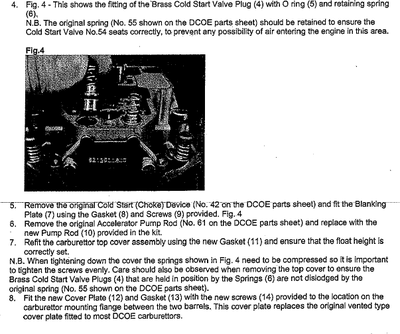
Oh and John one item you got wrong in your diagram (good guess though) is that the little pistons and springs do not replace the existing ones. You remove the cap that allows air to pass but retain the original piston and spring. Then the new ones sit on top. They have two purposes. The first is to block this as an airway - hence the o-ring. The second is to provide a greater pressure on the old pistons to hold them at the bottom. It is the action of replacing the top cover of the carb that compresses the new spring. You'll notice that these new ones are a. too short to do the full job and b. have a flat bottom as opposed to the taper of the originals so wouldn't actually seal the hole to the throttle barrel very well
Simon
'67 S3 FHC 36/7002
'69 +2 50/1370 (stolen '00)
'67 S3 FHC 36/7002
'69 +2 50/1370 (stolen '00)
-

simonknee - Third Gear

- Posts: 392
- Joined: 18 Sep 2003
Simon. Thanks for he corrections to my theory.
Ok?. Bang a Ball-Bearing into the air inlets next to the cold start jet. Sounds a bit drastic, the M5 Screw method might be more aesthetically pleasing !.... Interestingly, I have an old pair of 40DCOE18?s that must have been modified at some stage, as these air inlets have been filled with solder?..
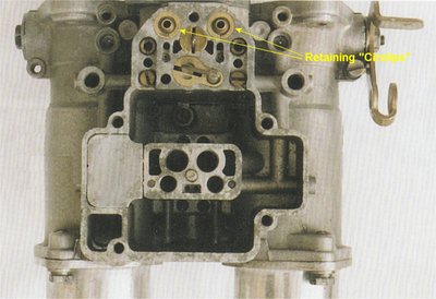
Also, the cold start ?Pistons? stay in place, complete with taper end for air sealing, and the new pistons-spacer's with seal and springs fit above them, holding them firmly in the closed position.
Just a thought on the latter. The small ?Brass Circlip? that retains the original Piston and Spring , would it be strong enough to retain the newly fitted spacer piston with seal, and the stronger spring ?....
John "Freddie" Nelson, Berks UK
26/5592 - Rebuilding
S4-Sprint DHC - Now at a new home.....
26/5592 - Rebuilding
S4-Sprint DHC - Now at a new home.....
- Fredtech
- Second Gear

- Posts: 68
- Joined: 19 Oct 2010
Simon,
Ah, great description. So, to summarize your comments (& others), we're dealing with two separate issues here:
1/ Leaks through the accelerator pump circuit caused by a vacuum building up behind the pump cover and sucking fuel into the chamber. It seems that the fuel mostly just sits there until the engine is switched off, at which point the vacuum decays and the fuel dribbles out. Drilling a hole in the pump cover prevents this.
2/ Leaks from the cold start circuit air intake caused by a high but correct fuel level in the float chamber (25mm), leading to fuel splashing around into the starter jet. Blocking off the cold start circuit will prevent this.
Is this right?
Being picky, I'd like to keep the cold start circuit, have the correct fuel level, and not have the leak. But it seems to be: take any two.
Nick
-

elanner - Fourth Gear

- Posts: 546
- Joined: 14 Sep 2010
John,
The springs are a bit stiff and the image provided in the instructions shows the top of the new piston sitting flush with the "deck" of the carbs. The new springs are poking right out.
Step 7 details ensuring that these springs compress properly.
Also note step 8 which now I re-read it assumes you have blanks with holes in so is providing blanks without. Seems odd in a way. However as fatboyoz says Weber never said why they started drilling the holes. There are other theories I have found on the web such as an ebay suppler who thinks it was to help with hot start issues.
So to answer Nick, Yes I think there are two issues, i.e. two locations at the back of the carbs that can weep fuel. As to whether this kit is designed to help with both issues - that's just a guess for now.
Summary 1 if we go by what fatboyoz found it is a little different to what you have written. He reckons that in instances of high vacuum, such as lifting off from full throttle, then air will be drawn into the barrels from anyplace it can be. Including from the spring chamber past the spindle bearings. Without the hole in the plate this creates a vacuum that in turn draws from where ever it can, this would include around the pump rod and it you follow that path you get to a source of fuel. Especially with old worn components.
What I can say is that fuel behind this plate will saturate the paper gasket and then seep out as soon as it can.
So this is a little contradictory - on one hand there is a pump rod to improve this area, yet on the other there are sealed plates! Yet of course underlying all this that Weber never said why they put the hole in the plate on later carbs, nor why they include the pump rod in this kit.
Summary 2. I'm not sure if the higher fuel level is solely responsible but I doubt it helps matters. I might formulate a better guess when I do the work.
EDIT: Of course there are no inboard bearings so you are relying on the tolerance between hole and spindle to prevent a vacuum. If there is a vacuum build up behind the solid plate then you run the risk of an air leak into the barrel with a holey plate... hmmm
Simon
'67 S3 FHC 36/7002
'69 +2 50/1370 (stolen '00)
'67 S3 FHC 36/7002
'69 +2 50/1370 (stolen '00)
-

simonknee - Third Gear

- Posts: 392
- Joined: 18 Sep 2003
simonknee wrote:EDIT: Of course there are no inboard bearings so you are relying on the tolerance between hole and spindle to prevent a vacuum. If there is a vacuum build up behind the solid plate then you run the risk of an air leak into the barrel with a holey plate... hmmm
Good point - and I considered this when I drilled holes in my plates. But I figured that if it proved to be a problem I would simply seal the holes or get another set of plates. As it turns out there was absolutely no difference in engine running that I could detect. Obviously if the spindle holes are very worn the situation might be totally different.
In my case I think the fuel buildup in the pump chamber was quite small. Perhaps a teaspoon after a long run. I don't know how much it leaked during the run, but it would certainly drip after the engine was switched off. That problem, at least, has now gone away.
On talking to some local guys with Weber experience about leaking the general comment seems to be "they all do that." Which is not quite the same as saying "they should all do that."
Never had to think about this stuff with my old Stromberg S4.....
Nick
-

elanner - Fourth Gear

- Posts: 546
- Joined: 14 Sep 2010
Not sure if it?s covered in the instructions BUT, the accelerator pump actuator arm sets the pump stroke which is model specific.
High wear in this area includes the brass liner the arm runs in, have spent many many hours looking into this leak problem, including fitting of oilite bushes on the inner spindle holes, and a ?O? ring for the pump actuator arm. Never did fix it completely!
FWIW
Ron.
High wear in this area includes the brass liner the arm runs in, have spent many many hours looking into this leak problem, including fitting of oilite bushes on the inner spindle holes, and a ?O? ring for the pump actuator arm. Never did fix it completely!
FWIW
Ron.
- Craven
- Coveted Fifth Gear

- Posts: 1624
- Joined: 14 Sep 2013
Hi Ron,
Thanks for the info. I found an Alfa thread where they fitted the elimination kit and the pump rod was wrong size for their Webers. Webcon swapped it for the correct one apparently.
In trying to fix the leak what was your thoughts/experience on the hole in the cover?
Thanks for the info. I found an Alfa thread where they fitted the elimination kit and the pump rod was wrong size for their Webers. Webcon swapped it for the correct one apparently.
In trying to fix the leak what was your thoughts/experience on the hole in the cover?
Simon
'67 S3 FHC 36/7002
'69 +2 50/1370 (stolen '00)
'67 S3 FHC 36/7002
'69 +2 50/1370 (stolen '00)
-

simonknee - Third Gear

- Posts: 392
- Joined: 18 Sep 2003
Hi Simon,
Well to cut a very long story short, I concluded that it was indeed some form of vacuum effect but had formed a theory that it was in some way associated with the fact a Weber is in fact a sealed unit and is operating at less than atmospheric pressure, to try an explain, the only air inlet to the float chamber is via a single hole at the rear usually up against and fed from the airbox, the depression within the airbox will therefore be transferred float chamber, when the engine is switch off this will rise to atmospheric pressure and push fuel out.
But could not get this idea to make any real sense and gave up.
Ron.
- Craven
- Coveted Fifth Gear

- Posts: 1624
- Joined: 14 Sep 2013
Springs eh, bloody springy them springs are. Take a while to find once they have sprung down the side of the engine too 
Back to the beginning...
So I unscrewed the covers on the Webers. Swapped in the fuel jet blanks. Swapped over the accelerator pump rods - my 40DCOE18 are the same size as the kit ones. I'll measure them later for others to refer to. Popped the discs on the cold start pistons being careful not to lose the springs (not daft me). Pushed in the extra piston with the o-ring and the extra spring on top. Boing. Out it pops again. New piston on the floor, long spring hiding beside the oil filter.
The o-ring does not grip enough to prevent the existing spring pushing the new piston back out. So there is a little game to play to get these in. You need to have the top cover ready and slide both pistons in underneath. Then jiggle away to get them to seat as you screw down the lid. Must remember to watch out for this when next I remove the covers.
So the eagle eyed will have spotted I did nothing about the airway. I am still contemplating which way to go - ball bearing, M5 tap, or perhaps just make a little plug of my own from something fuel resistant.
Anyway if the kit works I should have done enough to stop fuel getting through to the cold start chamber. Initially I am monitoring this by seeing if the gasket behind the blanking panel (the one that replaces the cog apparatus) now dries out. I have had blanks on for a year and the gasket is always visibly saturated with fuel - a tell tale sign that there is a build up behind the panel.
I'll report back as I get some more results.
Simon
'67 S3 FHC 36/7002
'69 +2 50/1370 (stolen '00)
'67 S3 FHC 36/7002
'69 +2 50/1370 (stolen '00)
-

simonknee - Third Gear

- Posts: 392
- Joined: 18 Sep 2003
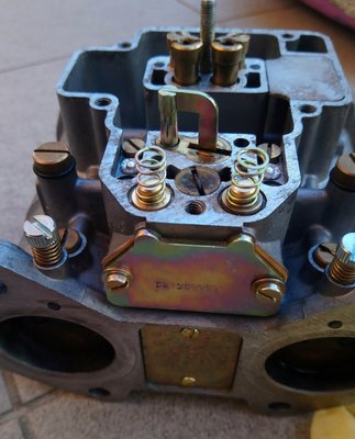
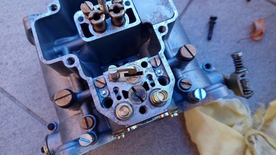
Hello,
I just fitted the cold start removing kit.
The result is too much fuel at idle... Richness 1.5 with volume screws closed!
My carbs are DCOE31.
I suppose fuel is leaking through the starter holes.
When removing the blocking plate, I see fuel inside, and also in the starter piston, which means fuel is still supplied by the cold start device OR sucked in from the throat.
Any ideas of what would be wrong? (started blank jets removed on the pictures)
Originaly the inspection plate is vented on my carbs, unlike the plates provided in the kit.
Thanks!
Caterham 1600K SS
Paris, France
Paris, France
- zimzum
- First Gear

- Posts: 34
- Joined: 29 Oct 2009
30 posts
• Page 2 of 2 • 1, 2
Total Online:
Users browsing this forum: No registered users and 33 guests

