Short block long stroke engine
If I were you I’d double check with the cam supplier that the compression ratio you are using isn’t too high for the fuel you intend to use. Sure you can get it to run ok without pinking by retarding the ignition but in my experience you loose a lot more power having to do that than by running a lower compression ratio in the first place. You have to allow a bit of margin for combustion chamber deposits that build up in the chamber during used. It’s better to be safe than sorry.
To me at least this is more important than worrying about whether you have 0.2 variation between cylinders.
To me at least this is more important than worrying about whether you have 0.2 variation between cylinders.
1970 Ford Escort Twin Cam
1972 Ford Escort GT1600 Twin Cam
1980 Ford Escort 2.0 Ghia
Peugeot 505 GTI Wagons (5spdx1) (Autox1)
2022 Ford Fiesta ST.
1972 Ford Escort GT1600 Twin Cam
1980 Ford Escort 2.0 Ghia
Peugeot 505 GTI Wagons (5spdx1) (Autox1)
2022 Ford Fiesta ST.
- 2cams70
- Coveted Fifth Gear

- Posts: 2162
- Joined: 10 Jun 2015
That sounds sensible. I subsequently double checked with cam supplier and he recommended 10.5, so it will need a few adjustments to hit that target.
Once the block has been squared up it will need some more measurements, but the options I can think of boil down to:
- With the thicker of the two gaskets, 10.3 CR and a squish band of approx 0.069"
- With the thinner of the two gaskets, take off a little from the piston intruder to give 10.5 CR and 0.053" squish
The second seems like the better option?
- ill_will
- Third Gear

- Posts: 265
- Joined: 18 Apr 2008
A couple of weeks back I did some other slightly more unusual measurements.
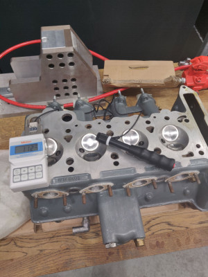
First off was hardness testing the new and old heads. The material spec for the new one is LM 25 TF, which looking it up is the hardest heat treated condition available for that casting alloy. One spec doc lists it as 100-110 Brinell (hardness.)
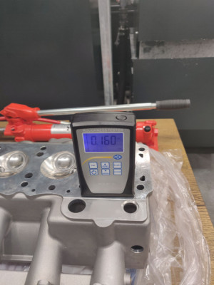
The portable tester we have at work (in fact, all hardness testers I've used) are slightly destructive, in that this one leaves a very slight indent in the surface. The test points were picked bearing that in mind. It works by firing a sprung loaded dart at the surface. The SAS head came in at 103 HB (nicely in spec) and the old one (I haven't checked exactly which alloy it is) came in slightly higher at 109 HB, which is good news.
I also did some surface roughness checks on both heads and the block. Predictably the SAS head casting quality is far superior, with no pinhole voids/inclusions visible compared with the original head (LP8226, I don't know if there was much variabillity with production date.) Sadly the decent portable roughness tester we have was broken, and the backup isn't great. The SAS head was around 0.2Ra whereas the old head was around 2.0Ra (NB it has been fitted but not run, and hasn't been skimmed.)
- ill_will
- Third Gear

- Posts: 265
- Joined: 18 Apr 2008
ill_will wrote:That sounds sensible. I subsequently double checked with cam supplier and he recommended 10.5, so it will need a few adjustments to hit that target.
Once the block has been squared up it will need some more measurements, but the options I can think of boil down to:
- With the thicker of the two gaskets, 10.3 CR and a squish band of approx 0.069"
- With the thinner of the two gaskets, take off a little from the piston intruder to give 10.5 CR and 0.053" squish
The second seems like the better option?
Agree second option is better. A thick gasket will probably be more difficult to source if the head ever has to come off again and the thicker the gasket the more likely it is to fail.
1970 Ford Escort Twin Cam
1972 Ford Escort GT1600 Twin Cam
1980 Ford Escort 2.0 Ghia
Peugeot 505 GTI Wagons (5spdx1) (Autox1)
2022 Ford Fiesta ST.
1972 Ford Escort GT1600 Twin Cam
1980 Ford Escort 2.0 Ghia
Peugeot 505 GTI Wagons (5spdx1) (Autox1)
2022 Ford Fiesta ST.
- 2cams70
- Coveted Fifth Gear

- Posts: 2162
- Joined: 10 Jun 2015
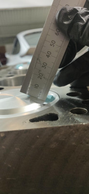
When I picked up the balanced crank assembly we had a go at levelling the block deck up, taking off the minimum possible. This was using promotor's technique with a ball bearing from the main cap bearing housing. It was pretty fiddly, both the measurements and also shimming the block in the deck grinding machine, but upon measuring afterward the discrepancy from cylinders one to four appeared halved compared to where it started, so movement in the right direction at least. For these checks, the same rod and piston was fitted to each cylinder in turn.
I then fitted the rods and pistons back in their original positions. Measuring from deck to the piston crown, even on the centreline, it was difficult to get a robust reading as the piston can rotate about the gudgeon pin quite a bit. This led me to measure to the centre of the intruder, using a DTI to find TDC for each. Taking repeated measurements of the same cylinder suggested measurement scatter of about a thou, and that #2 and #3 were within approx a thou of one another relative to the deck.
However, I found that #1 and #4 were still both 0.003" different to #2/ #3, in opposite directions. Swapping the rod and pistons between 1 and 4 improved things significantly (I swapped them back again and confirmed that the discrepancy reappeared.) I suspected the rods, so swapped them over, but the problem remained, so finally, swapped the pistons over and all intruder centres were within approximately +/-0.001". Measuring the crown to deck heights in this final configuration confirmed this.
To be completely honest, I'm a little surprised with this conclusion as the other dimensions I've measured for the JE pistons are very consistent. I'm mindful that the measurement capability I have is pretty limited though, although I did a fair bit of A-B-A testing, and also tried to get a handle on variance through repeats. Either way, the situation now seems better than it was initially, with less than a third of the range in deck to crown height.
- ill_will
- Third Gear

- Posts: 265
- Joined: 18 Apr 2008
Started a trial build, to find other issues. So far:
- Bottom end clearance all checked at 0.060", with one exception. I started off with feeler gauges but this was a PITA. Brass wire of the right gauge made things a lot easier.
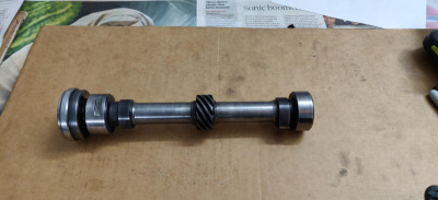
- The close call was rods to the jackshaft. I need to take off about 0.1" off the diameter of it to give 0.060" clearance. I called in at Gosnays but they said they can't do it. I got another rough quote for £200 which sounds high given what is involved.
- Three of the head stud washers/nuts clashed. The ARP washers are slightly larger diameter (and thinner) than the original ones off the engine. Two require a small flat to be ground on one side to clear the cam endfloat ring and a cam cap. The biggest issue by far is the exhaust cam cap furthest from the timing case. This required careful filing: the nut, washer and slim socket all initially clashed with it. I vaguely remember stopping these rotating when torquing the bolts up is a pain.
- The chain tensioner piston doesn't fit. I'm going to order a new one and check that. It doesn't look like I can access it from the 'inside' to ream it so if this is needed to open out the plunger bore slightly I guess I have to go from the outside and take a little off the thread itself(?)
- Fitting new thrust bearings caused the crank to bind. They are very close thickness to the old ones, which seem in good condition, so I'm going to run the old ones, which don't bind. Looking at them I think it must be the lack of chamfer on the edge that sits against the crank journal radius. The endfloat is a little under spec, at 0.002", but will hopefully be ok.
Another job was to fit the cams one at a time and time up the #4 valves to approximately the correct lift at TDC (0.108".) I didn't have the exact spec but used a similar Newman cam which is about the same lift and duration. I put a mark on the inner part of the vernier, so I can get the timing in the ballpark for doing a clearance check with plasticine. The cams will be timed with a degree wheel properly when setting it up for real.
- ill_will
- Third Gear

- Posts: 265
- Joined: 18 Apr 2008
I'm surprised you went to all that trouble to get your piston heights equalised but don't seem too concerned about your crankshaft thrust clearance being out of spec.
1970 Ford Escort Twin Cam
1972 Ford Escort GT1600 Twin Cam
1980 Ford Escort 2.0 Ghia
Peugeot 505 GTI Wagons (5spdx1) (Autox1)
2022 Ford Fiesta ST.
1972 Ford Escort GT1600 Twin Cam
1980 Ford Escort 2.0 Ghia
Peugeot 505 GTI Wagons (5spdx1) (Autox1)
2022 Ford Fiesta ST.
- 2cams70
- Coveted Fifth Gear

- Posts: 2162
- Joined: 10 Jun 2015
2cams70 - I saw your response and initially thought it was odd quibbling over half a thou.
Then double checked and realised I'd got the spec for end float in my notes wrong. I will investigate further. Hoping it is the crank corner radius and putting a slight chamfer on the edge of the bearing will sort it.
Then double checked and realised I'd got the spec for end float in my notes wrong. I will investigate further. Hoping it is the crank corner radius and putting a slight chamfer on the edge of the bearing will sort it.
- ill_will
- Third Gear

- Posts: 265
- Joined: 18 Apr 2008
It took a while to find someone local with a lathe to turn down the jackshaft but now it's done. He ended up taking off two of the lobes, so unfortunately it will be a bit out of balance, but it should be quite a small amount, given it's going at half crank speed.
- ill_will
- Third Gear

- Posts: 265
- Joined: 18 Apr 2008
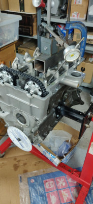
Recent progress has involved timing up the cams and doing a trial build, to check clearances with plasticine.
This was the first time I'd timed cams up with vernier pulleys from scratch - I learnt a few things along the way which may be of use to someone doing the same job. There are some good descriptions on here so I will try not to repeat what I've read elsewhere.
To get started, I put the head onto the block with the pistons half way down the bores. Cams not fitted. Then tightened the cam caps down for one cam at a time, with the #4 lobes pointing inwards.
The lift at TDC specs for these particular cams are approx 0.15". I made up an extension for a DTI approx 150mm long and 3mm diameter from a bit of stainless rod. On each tappet top, there seems to be one spot of the four available that is easier to get the extension onto, perpendicular to the tappet top.
On the number 4 cylinder, I rotated the cam to get the approximate correct amount of lift at TDC and then scribed a line on the inner part of pulley where the standard timing marks are, to give me a ball park setup. Then removed the cam, and repeated on the other.
In retrospect, this was maybe unnecessary, but did give me a bit of confidence as I was paranoid about damaging the valves. I also tightened down the cams with the head off the block (lobes inwards on #4) to see how close the two valves got to each other on overlap (approx 0.95mm iirc.) These timing marks let me position the cams slightly conservatively when setting up the chain over the pulleys: advancing the exhaust and retarding the inlet.
I did the clearance checks at In 100 and Ex 102 deg, and found that with the pistons and cams I'm running there was actually plenty of clearance (~2.5mm min.) I then dialled in the target timing 106/109 degrees and tightened the pulleys which will hopefully be pretty close when I assemble it for real.
- ill_will
- Third Gear

- Posts: 265
- Joined: 18 Apr 2008
Firstly compliments to you for continuing to tell your story. It takes time to think of the words and put them down and also take a few pictures. There’s many cases of beginnings on this forum but no endings.
One concern I do have however is that your jackshaft has only one groove for pumping oil to the head. It should have four so your jackshaft has been made from a standard pushrod engine camshaft not a twin cam jackshaft. I’d suggest that you need to attend to that issue and whilst there complete the job of taking off the lobes and remove all of them not just two.
One concern I do have however is that your jackshaft has only one groove for pumping oil to the head. It should have four so your jackshaft has been made from a standard pushrod engine camshaft not a twin cam jackshaft. I’d suggest that you need to attend to that issue and whilst there complete the job of taking off the lobes and remove all of them not just two.
1970 Ford Escort Twin Cam
1972 Ford Escort GT1600 Twin Cam
1980 Ford Escort 2.0 Ghia
Peugeot 505 GTI Wagons (5spdx1) (Autox1)
2022 Ford Fiesta ST.
1972 Ford Escort GT1600 Twin Cam
1980 Ford Escort 2.0 Ghia
Peugeot 505 GTI Wagons (5spdx1) (Autox1)
2022 Ford Fiesta ST.
- 2cams70
- Coveted Fifth Gear

- Posts: 2162
- Joined: 10 Jun 2015
Ha! Yes, I'm trying to keep the story going. It has been quite useful being able to look back through some of the older posts. And hopefully useful to someone else planning a similar DIY build. People's observations and comments on things I've missed have been invaluable too.
The jackshaft actually has three grooves, just a bad camera angle. I'm aware the standard Lotus part has four. I could run a shallow groove round the whole thing to give continuous feed, or leave it as is. I don't have a feel for whether three grooves will be adequate to be honest.
The jackshaft actually has three grooves, just a bad camera angle. I'm aware the standard Lotus part has four. I could run a shallow groove round the whole thing to give continuous feed, or leave it as is. I don't have a feel for whether three grooves will be adequate to be honest.
- ill_will
- Third Gear

- Posts: 265
- Joined: 18 Apr 2008
Another unwelcome development was the arrival of a Cometic CFM 84mm gasket, 0.043" thick. I measured the fire ring diameters and found they were ovalised and undersize, at 83.5mm in the crank direction, close to 84mm in the thrust direction. The gasket is well located on the ARP studs, but in a couple of places the fire rings very slightly overhang the bore, in part due to the undersize. Additionally there was no cut out for the oil drain pipe, but that could be solved if necessary.
Has anyone else found this with these gaskets? I don't think they have an 85mm version in CFM, unfortunately. I may try the Adjusa 84mm composite type next then.
Has anyone else found this with these gaskets? I don't think they have an 85mm version in CFM, unfortunately. I may try the Adjusa 84mm composite type next then.
- ill_will
- Third Gear

- Posts: 265
- Joined: 18 Apr 2008
Total Online:
Users browsing this forum: No registered users and 9 guests

