Short block long stroke engine
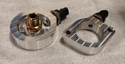
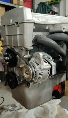
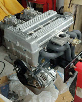
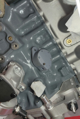
I'm starting to turn my attention to fuel injection. Made up a couple of sandwich plates to mount temp/pressure sensors for oil at the filter, and coolant at the thermostat. I will keep the mechanical gauges too on the dash, these will be for the ECU only.
- ill_will
- Third Gear

- Posts: 264
- Joined: 18 Apr 2008
I've been following this thread with interest and its looking really good!
I would be very interested in your fuel injection setup as I'm just about to go down this route with Jenvey heritage ITB's with an existing MBE ECU.
I'm also rebuilding the twink with a steel bottom end and short duration high lift cams. When I say I'm building it, actually its James Goldstraw of Grace Engineering doing most of the work and I noticed you had your crank balanced there!
- Europa88
- First Gear

- Posts: 48
- Joined: 23 Dec 2020
Hi Europa88,
Thanks for posting. I enjoyed dealing with James - he appears to take pride in his work and is very knowledgeable, and he listens too. The only snag for me is getting to his workshop is a bit of a nightmare from where I live.
I was initially thinking of using Jenvey heritage throttle bodies. They look great (I want to try to keep things looking stock) but they are extremely expensive. Two (at least) other considerations I am undecided on:
- Part throttle tuning. To do this well some tuners recommend a hybrid of alpha N at wider throttle openings and MAP at light openings, (if the ECU supports it.) The latter via a vacuum balance bar. Drilling the head is a no no for me; I'm not sure if the heritage bodies have bosses suitable for drilling. Many of the other ITB options do not have bosses, so I'm not totally sure how to solve this one.
- Idle control. I suspect timing based idle control won't be great during cold start up. With - say - throttle by wire this problem is solved, but this isn't a route I want to take. Also not that easy with an ICV without post-throttle bosses.
I'm playing around at the moment with the idea of a plenum arrangement. Not saying I'll go down this route, but haven't ruled it out! If anyone has tried one on a twin cam I'd be interested to hear.
Cheers,
Will
- ill_will
- Third Gear

- Posts: 264
- Joined: 18 Apr 2008
Hi Will,
James is true pro and a hidden gem IMHO.
My ECU is very limited it what it can do, cutting edge in its day which was 20 years ago. I will go with Alpha N (The heritage bodies have an inbuilt tps) I’m not going to run closed loop so in theory I don’t need Lambda, only ambient air and coolant sensor. I’m already running wasted spark and have a base map for fuel so I’ll try this route first. I have added a Barometric sensor just in case I travel to any mountainous regions.
I’m planning on running a swirl pot and a lift pump rather than a deadhead system as my car is a Europa and being mid engined gets very hot at low speed. If the fuel evaporates in the fuel line the air can only go through the injectors, whereas with a return to swirl pot and / or tank it’s not an isssue.
I’m only up the road in Oxford from James so not too bad.
If any one is interested he is going to video the whole rebuild and put it on YouTube
Cheers
Neil
- Europa88
- First Gear

- Posts: 48
- Joined: 23 Dec 2020
Hi Neil,
That all sounds sensible. I guess if you're needing to modify the loom at any point you could always add some additional wires to future proof it should you change ECU or add sensors further down the line.
I came to the same conclusion as you on the fuel return, but plan to run an in-tank pump (an Elise S1 unit.)
Please encourage James to do a twin cam video, the more detailed the better! There isn't enough high (quality) content on the twin cam (or elan restoration in general tbh.) Making videos must take up a lot of time though so understandable.
Cheers,
Will
- ill_will
- Third Gear

- Posts: 264
- Joined: 18 Apr 2008
A little more progress.
Designed a cam position sensor to fit in place of the distributor and 3D printed it to test fit. It runs a modified standard shaft and end gear in two shouldered bronze oilite bearings. There is a hall effect sensor and a rotor arm with a permanent magnet inside.
Finding a small flange mount connector was tricky. The smallest I could find was an autosport ASX series three pin but these are a pain due to the crimping tools needed which I will need to borrow.
I'll post a few more photos when I've machined it.
- ill_will
- Third Gear

- Posts: 264
- Joined: 18 Apr 2008
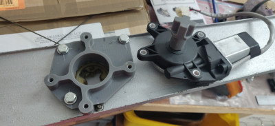
Not really related to this thread but at the same time I prototyped some window winder motor adapter plates. These plates adapt the 20 quid motors that one of the robot shops sells to suit the S3 window frames. The concept is similar to others I've seen on this forum, so thanks for the inspiration!
The driveshaft of the motor is quite easy to remove from the gearbox housing and it seemed easiest to replace with a custom driveshaft.
The parts are 3D printed for testing.
I might try machining the driveshafts from 7 series to start with. If there is a fatigue failure then steel.
The plate will be 5 or 6 series depending on what scrap I have lying around.
With the epoxy parts the window goes up and down much more briskly than previously, but I managed to shatter the first driveshaft when hitting the end stop.
- ill_will
- Third Gear

- Posts: 264
- Joined: 18 Apr 2008
I had a day off so programmed up the next few parts to run on the mill.
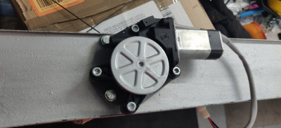
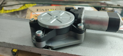
This is the window motor adapter drive shaft fitted vs how it came.
And the bracket assembly and motor fitted (sorry I didn't take a photo without the motor fitted, but I need to program the opposite side up and make that so will try to photo that one.)
The complete assembly is about half the weight of the original motor (which is about 1.4kg) and is quicker than the original.
I tested stalling it fully closed directly connected to the battery; it popped a 5A bullet fuse but an 8A fuse was fine for 10 seconds or more.
- ill_will
- Third Gear

- Posts: 264
- Joined: 18 Apr 2008
It’s a design requirement of modern cars that power windows can sense when there is an impediment to movement and automatically retract. This is done to minimize the risk of injury and strangulation of children. Perhaps it’s something worth thinking about in your design. It’s admirable what you’ve achieved so far though.
1970 Ford Escort Twin Cam
1972 Ford Escort GT1600 Twin Cam
1980 Ford Escort 2.0 Ghia
Peugeot 505 GTI Wagons (5spdx1) (Autox1)
2022 Ford Fiesta ST.
1972 Ford Escort GT1600 Twin Cam
1980 Ford Escort 2.0 Ghia
Peugeot 505 GTI Wagons (5spdx1) (Autox1)
2022 Ford Fiesta ST.
- 2cams70
- Coveted Fifth Gear

- Posts: 2160
- Joined: 10 Jun 2015
Hi Will,
In my experience of running with ITB’s and a TPS, good part throttle tuning can be achieved provided the engine is properly mapped. That is the whole map is adjusted and not just the top third that will give a good BHP curve print out. This takes dyno time and time equals money.
The idle after a cold start, without an IACV, is not too much of an issue, I have found that a slow idle can be maintained down to about 5deg C. As the engine is then getting warmer the problem goes away. I do have the idle set quite fast at 975 rpm. As the cold start setting is up to you an ECU with some sort of logging and a Lambda sensor fed into the ECU is very helpful.
Keep up the good work, I do like some of the parts you are making.
Cheers
John.
- elanman999
- Fourth Gear

- Posts: 500
- Joined: 12 Nov 2005
Hi John,
Thanks for the comments. There are a few reports (yourself included) which suggest that a TPS based approach will give good results. Thanks for the data point on cold start.
My current thinking is either to package protect for an IACV, or to include a small stepper mechanism which can make very small adjustments to the throttle position stop (i.e crack the throttle open very slightly.)
The other big design decision is that I haven't totally ruled out a plenum. I was looking at how the air path kinks at the DCOE mounting flange and thought it could be better designed. Currently the chassis and body of the car are several hours from my garage with the engine in so I can't measure it up to progress though.
Cheers,
Will
- ill_will
- Third Gear

- Posts: 264
- Joined: 18 Apr 2008
When I was at the factory today I programmed and ran the other window motor bracket. This is after the first operation:
And after the second:
The design was originally tweaked so that the base has two parallel edges so it is easy to hold for the second op and no bespoke fixturing is required.
You might be able to see that the main bore is roughed and finished all the way through the part, so in the second op you can pick up the position from this bore and the horizontal face of the jaw which the part sits on. This should give maybe 20 micron accuracy between the two ops which is enough for this part. Total milling time was maybe half an hour including probing the datum for the second op.
The threads are cut with a thread mill and it is fully deburred on the machine, so basically ready to fit I hope. I say I hope because I don't have the other door frame in my garage so am just hoping it is close enough dimensionally to the one I do have, which is not a given with anything Lotus made at this time!
- ill_will
- Third Gear

- Posts: 264
- Joined: 18 Apr 2008
Whilst at the factory last week I programmed and ran a couple more parts. The more interesting is an adapter plate to allow a high pressure return type fuel injection pump to be fitted inside the standard tank (repro aluminium tank actually.)
I've read of a few people doing this already, but couldn't find any off the shelf adapter or pump that seemed to address my main concern, fuel starvation.
The other main aims were/are to give a fairly flat boot floor, keep it as stock looking as possible, get cooling and noise reduction via in tank rather than external pump, minimise the number of connectors.
I found an uprated Elise pump which was approximately the right height and has a spring load arrangement to press it firmly on the base of the tank. It also has a reservoir with non return valve and what they call an 'eductor' which apparently fills the reservoir indirectly. I havent tested this aspect of it but it appears to use some kind of venturi-like effect to do this. The return also dumps fuel in the reservoir.
This is the adapter:
It is 6082 and the plan is to TIG it into the top of the tank (not me!)
With the pump fitted. It takes the push-release type connectors which are found on many production cars, to suit nylon hose. It looks like these can be fitted carefully with a hot air gun.
I need to make up the clamp ring next.
- ill_will
- Third Gear

- Posts: 264
- Joined: 18 Apr 2008
Total Online:
Users browsing this forum: No registered users and 10 guests

