Correcting Oil Leaks
22 posts
• Page 1 of 2 • 1, 2
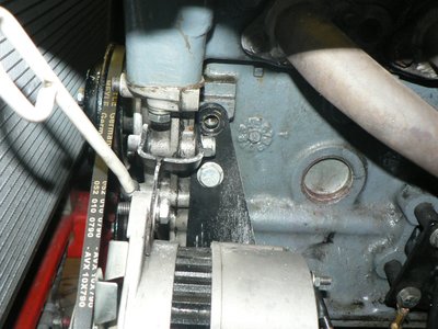
The main oil leak seems to be coming from the front cover / head / block joint on the alternator side. As ever it is difficult to pin point exactly. I ran it for 10 minutes after cleaning it all and oil was visibly gathering at the bottom of the alternator to block bracket.
So it looks like I'll have to remove the Burton modular water pump. It should be possible by just dropping the front of the sump. (?)
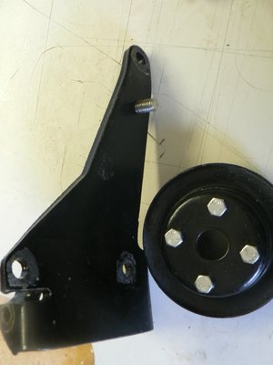
There is also a bolt missing of the top of the alternator bracket - I take it this is not vitally important? It's at that point that the leak appears.
I've never removed the front before so any problems I should look out for?
1. Remove water pump cassette
2. Remove chain tension bits.
3. Does the tension idler gear come off with the front cover?
I also intend to retorque the head before resetting the valve clearances. Crack off the bolts a quarter turn before retorquing. Is that the approved method?
So -
I. Do the front / water pump .
2. Remove cams and retorque head and the 3 front cover bolts.
3. Turn to TDC, refit cams and check clearance.
4. Remove cams and correct.
5. Correct cam timing.
I've started a wall chart of spider cartoons. At each correction I can cross out a "spyder".
It keeps me focused!
Vince
Last edited by vincereynard on Thu Mar 16, 2017 4:20 pm, edited 1 time in total.
- vincereynard
- Coveted Fifth Gear

- Posts: 1071
- Joined: 12 Jan 2015
Hi Vince
Your alternator bracket looks like a bodge?
Its a late Ford alternator bracket (not the Lotus one) and is supposed to connect with the top bolt into the block but does not line up for some reason. It appears another bolt has been fitted into the bracket below the original hole but it is not clear what it connects to behind the bracket as the block has no locating hole at that point ?
cheers
Rohan
-

rgh0 - Coveted Fifth Gear

- Posts: 8417
- Joined: 22 Sep 2003
vincereynard wrote:There is also a bolt missing of the top of the alternator bracket - I take it this is not vitally important? It's at that point that the leak appears.
I might suggest you install the bolt and see if the leak disappears. Since that's where the leak appears it just might be vitally important.
Of course, if you just want to do all the other work . . . . . .
Charlie Warner
Fatto Gatto Racing
Fatto Gatto Racing
-

fattogatto - Third Gear

- Posts: 252
- Joined: 23 Sep 2015
rgh0 wrote:Hi Vince
Your alternator bracket looks like a bodge?
Its a late Ford alternator bracket (not the Lotus one) and is supposed to connect with the top bolt into the block but does not line up for some reason. It appears another bolt has been fitted into the bracket below the original hole but it is not clear what it connects to behind the bracket as the block has no locating hole at that point ?
cheers
Rohan
Spot on! The bolt simply screws into the bracket and does nothing! The top does virtually line up its just the parallax that makes it seem out. However the "spare" bolt is too long. Fairly typical Spyder careless error - perhaps merely practice for their others.
fattogatto wrote:vincereynard wrote:There is also a bolt missing of the top of the <a class="vglnk" target="_blank" href="http://www.ebay.com/sch/i.html?_nkw=alternator" rel="nofollow"><span>alternator</span></a> bracket - I take it this is not vitally important? It's at that point that the leak appears.
I might suggest you install the bolt and see if the leak disappears. Since that's where the leak appears it just might be vitally important.
Of course, if you just want to do all the other work . . . . . .
The empty hole is simply a blind thread, it shouldn't have any connection to oil. Also the hole itself is dry.
- vincereynard
- Coveted Fifth Gear

- Posts: 1071
- Joined: 12 Jan 2015
Would it hurt? Consider clamping force in that area. If it works wouldn't it be a cheap fix?
Charlie Warner
Fatto Gatto Racing
Fatto Gatto Racing
-

fattogatto - Third Gear

- Posts: 252
- Joined: 23 Sep 2015
fattogatto wrote:Would it hurt? Consider clamping force in that area. If it works wouldn't it be a cheap fix?
I've now stripped it down twice. Firstly clean it up, then built up and ran to try and spot the leak. Now stripped to correct the water pump problems.
So it wouldn't hurt - if I had been smart enough to spot it before.
- vincereynard
- Coveted Fifth Gear

- Posts: 1071
- Joined: 12 Jan 2015
It's an opportunity to examine the beast. You might find other issues. Good luck.
Charlie Warner
Fatto Gatto Racing
Fatto Gatto Racing
-

fattogatto - Third Gear

- Posts: 252
- Joined: 23 Sep 2015
fattogatto wrote: You might find other issues.
Given recent experience, and the inept hand of Spyder, that is most likely!
- vincereynard
- Coveted Fifth Gear

- Posts: 1071
- Joined: 12 Jan 2015
Hi Vince
I've never tried it with a Burton cover, & it may be different to a std cover, but it is possible to remove & refit the cover by simply dropping the sump, I have done it in the past. But, it isn't really the way it should be done. The head should be removed also as there is a timing chain slipper attached to the cover that protrudes up in to the head, meaning the cover has to be lowered before it can be withdrawn. this is where the problems start with the std cover, as the water pump pushes in to the rear half of the front cover with an 'O' ring, meaning the cover has to be withdrawn before it can be lowered. This may not be the case with the removable water pump. The tensioner wheel pivots from the head & hangs down in to the timing chest, so can be left, but the adjuster should be removed. It can be 'wriggled' out, but it's all a bit tight, & trying to get it all back together keeping the cork gasket (which you will have to cut, as part of it is trapped by the rear half of the cover) in place & without destroying it is, shall we say, not easy, & if the object is to cure oil leaks.....
When setting the valve clearances, I always set the pistons such that all 4 are about half way up/down their stroke. With the chain removed, you can then turn each cam shaft with a spanner to check each valve in turn. With no pistons near the top, all valves have plenty of room to open without getting anywhere near them. Once finished, set the cams on their marks, then turn the engine to TDC in the normal direction of rotation & refit the chain.
Regards, Tim
- Orsom Weels
- Third Gear

- Posts: 409
- Joined: 31 Oct 2011
Cheers Tim,
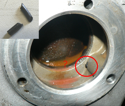
Things move on and it look like a head off job anyway as the leak appears to be the back cover / head joint. (The famous cork gasket) I shall probably have to take the front timing cover off anyway as todays find is a bit of, what looks like, O ring stuck between the covers.
Normal Spyder casual carelessness? Should it even have an O ring there? I don't see why.
For future reference, what is the advised manner of attaching the timing disc? Access to the crank pulley bolt is a necessity obviously so how is it fixed?
Vince
- vincereynard
- Coveted Fifth Gear

- Posts: 1071
- Joined: 12 Jan 2015
Hi
I stick the timing disc to the crank pulley bolt with industrial bluetack works for me.
The most common leak around the front is from the cork gasket, don't use silicon adhesive, I use 80019A Permatex Aviation forma-gasket No3 sealant, again it works for me
Do the job properly and it pays off
Good luck
John
+2s130 1971
+2s130 1971
-

Hawksfield - Fourth Gear

- Posts: 603
- Joined: 14 Jul 2004
vincereynard wrote:.......O ring stuck between the covers..............Should it even have an O ring there? I don't see why.
e
Yes there is an O ring between backplate and front cover on the Burton arrangement to keep oil and coolant apart. It fits in a machined channel, but clearly in your case it has slipped out and trapped on assembly.
Looks like you are using modern OAT coolant, it may damage the old radiator / heater cores with brass/solder construction, unless they have been replaced with aluminium radiators.
Malcolm
1966 Elan S3 Coupe
1994 Caterham 7
1994 Caterham 7
- englishmaninwales
- Fourth Gear

- Posts: 710
- Joined: 26 Jul 2013
Hawksfield wrote:Hi
I stick the timing disc to the crank pulley bolt with industrial bluetack works for me.
The most common leak around the front is from the cork gasket, don't use silicon adhesive, I use 80019A Permatex Aviation forma-gasket No3 sealant, again it works for me

Good luck
Thanks for that, I take it you still use gaskets, just coat both sides with this stuff?
Do the job properly and it pays off!! I don't have to suggest who you should give that message!
englishmaninwales wrote:Yes there is an O ring between backplate and front cover on the Burton arrangement to keep oil and coolant apart. It fits in a machined channel, but clearly in your case it has slipped out and trapped on assembly.
Looks like you are using modern OAT coolant, it may damage the old radiator / heater cores with brass/solder construction, unless they have been replaced with aluminium radiators.
Malcolm
Thanks Malcolm. I have just examined an image of the back plate and the ring groove is clear.
http://www.burtonpower.com/back-plate-f ... l843t.html
Just poor assembly then. So all that will have to come off as well as the head.
Strange it must have been visible before slipping the cassette in.
It does have a posh new alloy radiator and remote filler. It hardly seems to get above 70 degrees.
Is it a known problem with the long life stuff?
Vince
- vincereynard
- Coveted Fifth Gear

- Posts: 1071
- Joined: 12 Jan 2015
Hi!
Just a quick minor point for future possible leaks while you are at it, to maybe add a breather to the front center of the cam cover to vent off some of the pressure in that part of the engine.
Cheers
Just a quick minor point for future possible leaks while you are at it, to maybe add a breather to the front center of the cam cover to vent off some of the pressure in that part of the engine.
Cheers
- blacklotus
- First Gear

- Posts: 19
- Joined: 21 Mar 2010
blacklotus wrote:Hi!
Just a quick minor point for future possible leaks while you are at it, to maybe add a breather to the front center of the cam cover to vent off some of the pressure in that part of the engine.
Cheers
An interesting thought. Why front center of the cover? As its open all the way up , wouldn't a vent on the cam cover work as well? Perhaps routed to a small catch tank?
- vincereynard
- Coveted Fifth Gear

- Posts: 1071
- Joined: 12 Jan 2015
22 posts
• Page 1 of 2 • 1, 2
Total Online:
Users browsing this forum: SENC and 28 guests


