Cooling system robustness improvements.
19 posts
• Page 1 of 2 • 1, 2
Given the price of cylinder heads I wish to do everything I can to limit the chances of cooking my engine. (no problems at the moment but even the slightest loss of coolant seems to a noticible rise in engine temperature)
Yesterday I fitted one of the Thermostat housings of of an Escort with the filler cap in the top (still available from ford finis 6101210) apart from a sheared bolt which I ended up replacing with a larger diameter stud (this had already been done to the other one) it went well, I have also blanked off the original radiator cap completely.
Looking t my TR7V8 got me thinking would it not be better to also fit one of the header tanks from the TR7/8 (brass type that looks like a squshed rugby ball) high at the rear of the engine compartment , T it into the bottom hose replace the the cap on the engine with a plain cap and connect the vent to the tank, some of the tanks even had level sensors which if I could get to work would really give some confidence.
Has anyone done this or something similar?
- kstrutt11
- Third Gear

- Posts: 316
- Joined: 27 Jun 2007
Have a look over this thread, I fitted the BMC 1100 tanks to my cars.
elan-f15/header-tanks-expansion-bottles-t20342.html
elan-f15/header-tanks-expansion-bottles-t20342.html
Brian
64 S2 Roadster
72 Sprint FHC
64 S2 Roadster
72 Sprint FHC
-

types26/36 - Coveted Fifth Gear

- Posts: 3407
- Joined: 11 Sep 2003
KSTRUTT (Kevin?), for a remote header tank to work most effectively I believe it needs the following:-
1/ small diameter line from top of radiator to allow for continuous purge/bleed of any air trapped in the radiator back to the header tank.
2/ some baffling/quelling in the header tank to ensure air/vapour release.
3/ a slightly larger line back to the pump suction (thus returning the purge/bleed liquids from the header tank back to the cooling system proper.
The header tank runs at system pressure (ie is the only place where a pressure relief cap is situated).
Having the pressure cap connected to the pump suction ensures the pressure cap does not relieve due to the pump differential head: it only sees the rise in pressure due to liquid expansion.
With this system, the entire cooling system should run without any trapped vapour reducing heat transfer efficiency. It's largely maintenance free because of the continuous bleed/recirculation.
Most modern cooling system are organised like this.
Can you make it work on a classic Elan? I would think you would need to get an additional fitting brazed to the top of the radiator but then again you might be able to use the existing fitting for the cap with a modified pressure cap.
To arrange a feed back into the pump suction, a tee'd fitting into the bottom hose might work...
Regards
Gerry
- gerrym
- Fourth Gear

- Posts: 882
- Joined: 25 Jun 2006
Kevin, the idea of the bleed CIRCUIT is that it isn't a static dead ended vent, but a continuously circulating system. Much more effective. For it to work, it must have a low pressure sink (the pump suction) to provide a pressure differential.
Do you have a modern, check t out and you will probably find something similar. By the way, this also eliminates the need for a separate vented overflow bottle. Thus no continuous ingress of oxygen into the system hence much longer life for the inhibitors. (or less scale and corrosion).
Regards
Gerry
Last edited by gerrym on Fri Sep 03, 2010 2:42 pm, edited 1 time in total.
- gerrym
- Fourth Gear

- Posts: 882
- Joined: 25 Jun 2006
Gerry,
Sounds like we are talking about the same idea, the vent pipe I was going to use is on the radiator side of the thermostat so would be low pressure. The thermostat housing I have is the one shown in the links above but I was planning to use just a plain cap rather than pressure cap so the vent would in effect be the highest point on the radiator top tank, I have found a T fitting to connect the bottom hose and somewhere to get the header tank and coolant sensor module from, just need the time now...
Kevin
- kstrutt11
- Third Gear

- Posts: 316
- Joined: 27 Jun 2007
Kevin, this is the cooling system that I have used on a Caterham for the last twenty years without any problems. The thermostat housing has a blanking cap fitted and the small bore hose is fed into the bottom of the plastic expansion tank (scavenged from a scrap Triumph iirc) tucked away in the nose of the car. The radiator has only top and bottom hose fittings.. there is no bleed fitting.
Cheers, Brian.
Cheers, Brian.
- ncm
- Third Gear

- Posts: 257
- Joined: 02 Jun 2006
The majority of the circuit pressure drop is across the heat exchanger (ie the radiator). So the sink for the circuit must be on the outlet (bottom connection) of the radiator, or inlet to water pump (same thing hydraulically speaking). A dead end high point vent is not the same as a circulating vapour release system.
Do you run a heater? The heater return goes back into the low pressure side.
Best regards
Gerry
PS, there's an awful lot of suggestions for bodged cooling circuits on this website. Not all will be an improvement over 1970 Lotus stock.
Do you run a heater? The heater return goes back into the low pressure side.
Best regards
Gerry
PS, there's an awful lot of suggestions for bodged cooling circuits on this website. Not all will be an improvement over 1970 Lotus stock.
- gerrym
- Fourth Gear

- Posts: 882
- Joined: 25 Jun 2006
I Had a better look today, there is not really any room to get a T piece in the bottom hose (no straight length), but Gerry's comment about the heater hose got me thinking, I will use the heater return hose on the back of the water pump housing and T into this, the feed will come from my new thermostat housing (which is adjacent to the heater feed hose), Just need to decide what to use as a warning, I'm erring towards the loudest buzzer I can find as I don't want to drill holes for a lamp.
Kevin
Kevin
- kstrutt11
- Third Gear

- Posts: 316
- Joined: 27 Jun 2007
You don't need to drill the dash for a warning lamp, do what I did and fit a LED into the chrome screw. It can barely be seen until lit. I use mine for an indicator repeater but I am thinking of using a two colour LED and use it as A fan warning light as well.
- Attachments
-
- finished screw.jpg (8.79 KiB) Viewed 3236 times
-
- Dash light 4.jpg (7.4 KiB) Viewed 3235 times
-
- Dash light 3.jpg (6.51 KiB) Viewed 3236 times
-
- Dash light 2.jpg (9.1 KiB) Viewed 3234 times
-
- Dash light 1.jpg (9.66 KiB) Viewed 3234 times
- elanmac
- Second Gear

- Posts: 58
- Joined: 04 Nov 2005
Wow,
That is a way cool way to add idiot lights without adding clutter to the dash. My car came with lights for low brake fluid, parking brake, and emergency flasher. Integrating those lights into the chrome screws that hold the dash in place is a brilliant idea! Sounds like something the hot rodders would come up with. Might do that when I redo my dash. Thanks for the idea.
That is a way cool way to add idiot lights without adding clutter to the dash. My car came with lights for low brake fluid, parking brake, and emergency flasher. Integrating those lights into the chrome screws that hold the dash in place is a brilliant idea! Sounds like something the hot rodders would come up with. Might do that when I redo my dash. Thanks for the idea.
Frank Howard
'71 S4 SE
Minnesota
'71 S4 SE
Minnesota
- Frank Howard
- Fourth Gear

- Posts: 919
- Joined: 30 Mar 2004
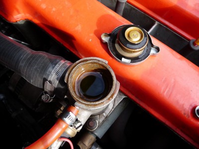
I cannot lay claim to any great knowledge of cooling systems, but the system in place on my +2 works and doesn't lose much water over time. It is a slight modification of the standard recuperative system, with one of the modified thermostat housings replacing the standard radiator cap. The fill point is the highest point in the system as the picture shows and purges air through the pressure relief pipe as the coolant expands, into the recuperator (sometimes called an overflow) bottle. As the engine cools, it is possible to see coolant flowing back into the engine through the clear hose I have fitted. The pipe connections must be air tight to the thermostat housing, not just a push fit that you often see. In use, the recuperator bottle has two levels - hot & cold, and keeping a regular eye on these is all I need to do. In practice I rarely take off the pressure cap unless the system is stone cold (overnight) as coolant will overflow the neck of the filler. The picture shows that the thermostat housing is at the top of the system and that there is no air in the system whatsoever. Coolant loss has been less than an eggcup full in 7,000 miles since the rebuild (car, not the engine) in March.
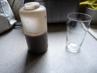
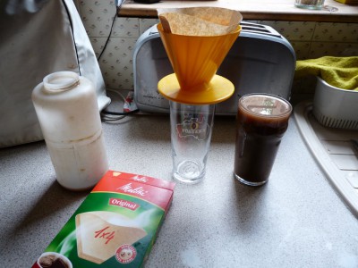
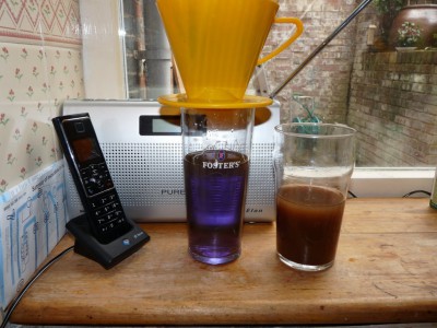
With time, there is a constant exchange of coolant between the engine and the recuperator bottle, which I've realised, can be used to your advantage by gradually removing sludge from the system. Every month or so, I take the bottle off the car, and filter the coolant as shown. This is best done when other members of the household are out of the house ? two hours is usually enough time. The filter paper will initially allow smaller particles through, but after the flow tails off to a drop or two a second the paper will be slightly clogged and filter the very fine particles out. Best to re-filter coolant which has not totally cleared when the paper is conditioned in this way. Eventually all the coolant will be clear and bright again, ready to go back into the bottle and from there into the engine. In a month or so, after fluid exchange cycles with the engine, the coolant in the bottle will be dirty again. After each filtering cycle, the sludge levels get less and less until the engine is clear of mobile sludge. In industry, this is similar to a process called ?side filtration? and can remove sub micron particles with no harmful chemicals etc, leaving clean, sludge free coolant. Its worth examining the sludge residue as this can tell you if there are any other contaminants such as oil, bits of gasket etc..
Of course, you could just keep flushing out the system, but this way, the coolant is retained and 'passivated'. Costs are limited to a coffee filter and dark looks from Mrs D if she comes home early.
Jeremy
Last edited by JJDraper on Fri Sep 30, 2011 8:48 pm, edited 1 time in total.
-

JJDraper - Fourth Gear

- Posts: 923
- Joined: 17 Oct 2004
Hey Jeremy,
Where did you get the "Elan" radio?
Where did you get the "Elan" radio?
Frank Howard
'71 S4 SE
Minnesota
'71 S4 SE
Minnesota
- Frank Howard
- Fourth Gear

- Posts: 919
- Joined: 30 Mar 2004
19 posts
• Page 1 of 2 • 1, 2
Total Online:
Users browsing this forum: No registered users and 5 guests


