Sprint Horn Push
4 posts
• Page 1 of 1
Greetings Fellow Elan'ers,
1. This thread concerns the elements comprising the particular Horn Push Assembly (I'm abbreviating it HPA) on the later model Elan Sprints, and will summarize my car's situation and my solution. Several of these pics, and some good background, are in this prior thread.
http://www.lotuselan.net/forums/viewtopic.php?f=38&t=42607
2. The "horn" on my '72 Sprint DHC didn't work. I figured out that the horns themselves (Hella, red, 3 trumpets and a compressor) worked, and the relay worked. I used a circuit tracer to verify the +12 "switch" circuit from the relay was going up into the steering column, and when it was grounded, the horns sounded.
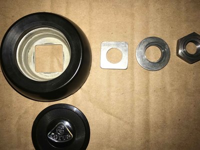
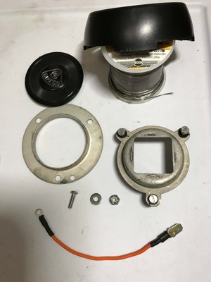
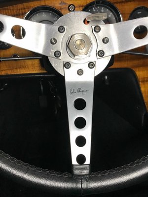
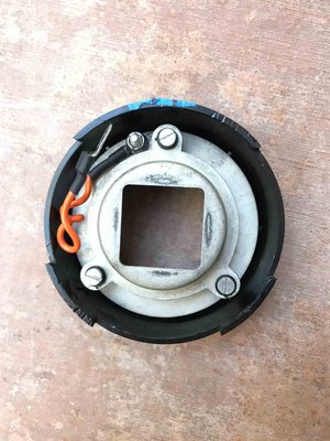
3. To remove the (original signed) Springalex steering wheel, I first pried up the flat cover (black plastic) having a small Lotus emblem. Then I removed the large nut, round and square washers, and the HPA (the "switch" mechanism), which is a clever arrangement of two concentric metal rings/cups, with spring-loaded plastic stand-offs keeping them electrically separate. The lower cup is both located and sandwiched to the top of the wheel hub by the two washers, and thus is grounded and rotates with the wheel.
4. Upon removing the HPA and the wheel, the slip ring was exposed at the top of the steering column. Fiddling with the HPA revealed that when its top edge is pushed, the upper cup compresses the spring(s) and contacts the lower cup, "closing" the switch.
5. The slip ring was connected to the horn relay circuit, but the in-between bits were missing: a springy contact to rub on the slip ring, a wire from the contact up through a hole in the steering wheel hub, and something to connect the wire/circuit to the upper concentric cup.
6. I contacted several companies regarding the original spec missing bits, desribed in the prior thread and including an arc of flat brass (the springy contact), curving around the steering wheel hub, mounted so as to rub on the slip ring. Alas, no joy. Also I got one of the springy "pencil" / "brush" tubes as used commonly on earlier Elans and many British cars, but decided it wouldn't work, due to the underside of the steering wheel hub having limited height and space, and my reluctance to alter any original pieces.
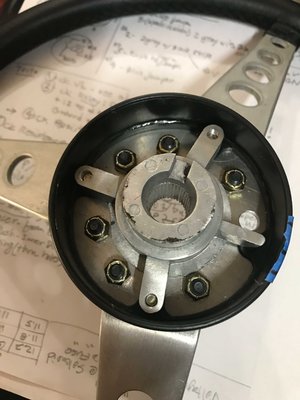
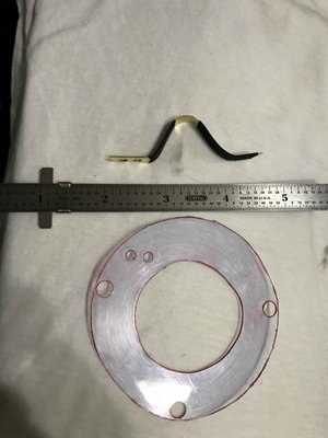
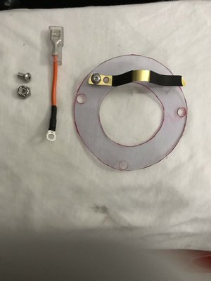
7. Eventually I got around to fabricating some pieces and getting it working. I opted for a straight (rather than arc'ed) brass contact strip, with one end secured to a plastic disc by two machine screws. The disc is held to the underside of the wheel hub by three nuts and longer black oxide cap screws (in lieu of the three shorter OE slot-headed steel screws), matching the other six screws. The other end of the strip is free to slide across the disc as the strip is depressed up by the slip ring.
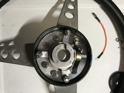
8. For the brass strip to have a good tangential-ish angle on the slip ring, it needs to be close to the (grounded) wheel hub, so I put shrink wrap over those parts of the strip. I soldered up two wires to get the circuit up to the "switch." Wire 1 has a ring terminal sandwiched under the brass strip, goes up through the hole in the wheel hub, and ends with an insulated female spade lug to protect the +12.
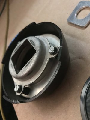
9. The next pic shows Wire 1 going through the hole in the hub (hard to see), and Wire 2 in the background. Wire 2 connects to Wire 1 with a male spade lug and ends with a ring terminal sandwiched to the upper cup.
10. In order to secure Wire 2 to the upper cup, I had to remove and separate the two cups. It was a bit tricky re-assembling them and maintaining their "insulation," as the plastic parts are somewhat worn.
11. Wire 2 is pig-tailed and, along with Wire 1's female lug, is stuffed in between the cups and the wheel hub, allowing the HPA to be lifted up and separated from the wheel.
12. Hopefully this thread will be helpful to others with similar situations. I'll be happy to answer any Qs or add even more boring details.
-Steve, SoCal, '72 Sprint DHC
formerly Lotus 47, Lotus Cortina
formerly Lotus 47, Lotus Cortina
-

nthSteve - First Gear

- Posts: 21
- Joined: 06 Jul 2018
EXCELLENT write up....and with pictures!
you don't happen to have an extra black plastic insert with Lotus logo (horn push disc)?
you don't happen to have an extra black plastic insert with Lotus logo (horn push disc)?
TED
"Driving a Lotus is a triumph of bravery over intelligence." Stirling Moss
"TaylorMadeClassicCars" on WWW and Facebook
"Driving a Lotus is a triumph of bravery over intelligence." Stirling Moss
"TaylorMadeClassicCars" on WWW and Facebook
- tedtaylor
- Fourth Gear

- Posts: 552
- Joined: 09 Dec 2012
Thanks Steve for this great idea.
My horn push has not worked for years and I have bypassed it and have a switch poking through the handbrake warning light hole to operate the horn which is not nearly as elegant a solution!
I will add your fix to my ?jobs to do? list
Richard
My horn push has not worked for years and I have bypassed it and have a switch poking through the handbrake warning light hole to operate the horn which is not nearly as elegant a solution!
I will add your fix to my ?jobs to do? list
Richard
Lotus Elan Sprint FHC 1973
-

RichardS - Third Gear

- Posts: 491
- Joined: 23 Apr 2007
4 posts
• Page 1 of 1
Total Online:
Users browsing this forum: No registered users and 14 guests


