Fuel gauge wiring question
5 posts
• Page 1 of 1
I have spent the last few months installing and checking a new wiring loom on my S3. What a PITA!. I have everything working except the horns and the fuel gauge.
The problem i'm having with the fuel gauge circuit is when I connect up the sending unit wires (black positive and green for the negative) all except 1 of the under dash green wires goes hot like there is no path back to the negative terminal. If I disconnect the sending, unit everything under the dash and the turn signals work fine.
I'm stumped. Any ideas what I'm missing?
Thanks,
Rick
- rcombs
- Second Gear

- Posts: 146
- Joined: 14 Jun 2013
Sounds like you have a short circuit somewhere. Possibly at the sender on the tank.
~~~~~~~~~~~~~
Oh perhaps you don't mean literally HOT as in temperature, may be you mean they all show 12 volts.
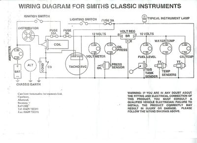
The basic wiring diagram for all the instruments is relatively simple. It only seems complicated when they draw them up with lines aligned like the looms; then they become hard to follow.
If you are adept with a multimeter, this should be all you really need. If you don't own a multimeter, stop now and go buy one, they are not expensive nowadays.
Bill Williams
36/6725 S3 Coupe OGU108E Yellow over Black.
36/6725 S3 Coupe OGU108E Yellow over Black.
- billwill
- Coveted Fifth Gear

- Posts: 4417
- Joined: 19 Apr 2008
rcombs wrote:The problem i'm having with the fuel gauge circuit is when I connect up the sending unit wires (black positive and green for the negative) all except 1 of the under dash green wires goes hot like there is no path back to the negative terminal. If I disconnect the sending, unit everything under the dash and the turn signals work fine.
Thanks,
Rick
I'm not sure exactly what you mean here, but it could be read like you're connecting a 12v live & earth to the sender ? If so, this is wrong & potentially very dangerous, this would turn the sender windings in to a heating element !
Simplified, as Bills diagram shows, the fuel gauge wiring consists of an ignition switched live to one side of the gauge, (Green wire), the other side of the gauge to sender, (Green/Black wire), & an earth connection to the sender, (Black wire). There should be NO live connection to the sender unit. (You don't say whether you have negative or positive earth, so I have referred to them as live & earth to avoid confusion.)
The sender is simply a potentiometer which varies the resistance to earth, the less fuel in the tank, the higher the resistance, & the less the gauge moves. If you connect the sender end of the Green/Black wire directly to earth, the gauge should read full.
The green wires under the dash should only be live, (or 'hot'), when the ignition is switched on, there should be nothing live to feed back from the sender unit to make them live ('hot')
Regards, Tim
- Orsom Weels
- Third Gear

- Posts: 409
- Joined: 31 Oct 2011
Thanks for the input. I finally figured the harness out. I new there were 3 green wires connected to the fuse box, I didn't realize they were not connected in the harness. Also the branch that connects to the gauges had to be connected externally to the one green wire that was connected to the fuse.
Now the only thing that is not working are the horns
Thanks,
Rick
Now the only thing that is not working are the horns
Thanks,
Rick
- rcombs
- Second Gear

- Posts: 146
- Joined: 14 Jun 2013
5 posts
• Page 1 of 1
Total Online:
Users browsing this forum: hibbs and 35 guests

