Hazard Warning Light - S4
16 posts
• Page 1 of 2 • 1, 2
Hi All,
I've read the archive and there appears to be a problem with the standard wiring. If the indicator is on, and the ignition is off, switching the Hazard switch on makes circuits live that shouldn't be.
There appear to be two solutions:
1. Replace the standard switch with a DPDT one and isolating the indicator feed
2. Using a diode in the indicator circuit to prevent the reverse feeding of the indicator circuit.
I prefer the Diode solution as it is simple and requires no alterations to the standard wiring. but I'm getting lost in the technicalities of diodes....
The normal load on the indicator circuit is 21W + 21W + 5W = 47W approximates to 4A at 12v
So I need a diode capable of handling 4A (lets say I need a 10A diode to keep the forward voltage down)
Can anyone recommend a suitable diode?
Will the indicators be significantly dimmer/slower?
Thinking further could I isolate the indicators feed with a relay powered from the hazard switch?
Anyone any other simple solutions?
- AHM
- Coveted Fifth Gear

- Posts: 1258
- Joined: 19 Apr 2004
This might be what you need but it does not say a rating,
http://www.autosparks.co.uk/product_inf ... ts_id=5257
Ring the company and ask, they have been helpful in the past.
Jon the Chief
http://www.autosparks.co.uk/product_inf ... ts_id=5257
Ring the company and ask, they have been helpful in the past.
Jon the Chief
- oldchieft
- Third Gear

- Posts: 375
- Joined: 17 Sep 2013
Try RS Components Pt # 7620169
PeterExpart
New Forest National Park
Hampshire UK
New Forest National Park
Hampshire UK
- peterexpart
- Second Gear

- Posts: 189
- Joined: 27 Nov 2012
Can't really advise, unless you show us the circuit that you are considering?
And I can't see where you get 21W+21W+5W from. Surely the Hazard warning lights all 4 trafficators, so the load should be 4*Bulb_rating.
And I can't see where you get 21W+21W+5W from. Surely the Hazard warning lights all 4 trafficators, so the load should be 4*Bulb_rating.
Bill Williams
36/6725 S3 Coupe OGU108E Yellow over Black.
36/6725 S3 Coupe OGU108E Yellow over Black.
- billwill
- Coveted Fifth Gear

- Posts: 4417
- Joined: 19 Apr 2008
billwill wrote:Can't really advise, unless you show us the circuit that you are considering?
And I can't see where you get 21W+21W+5W from. Surely the Hazard warning lights all 4 trafficators, so the load should be 4*Bulb_rating.
Hi Bill,
I'm using the S4 wiring diagram. The diode would go in the feed to the indicators, which only feeds one side at a time.
- AHM
- Coveted Fifth Gear

- Posts: 1258
- Joined: 19 Apr 2004
Jon,
I ordered from them just last week - I'll get the lights-on diode, for a lights on alarm anyway.
Peter,
That looks like the thing for the job. I suppose the way to find out if it dims or slows the lights, is to try.
Anyone know which hazard flasher I need?
I ordered from them just last week - I'll get the lights-on diode, for a lights on alarm anyway.
Peter,
That looks like the thing for the job. I suppose the way to find out if it dims or slows the lights, is to try.
Anyone know which hazard flasher I need?
- AHM
- Coveted Fifth Gear

- Posts: 1258
- Joined: 19 Apr 2004
This Hazard switch might help.
I haven't worked out yet what its wiring diagram does.
http://www.holden.co.uk/displayproduct. ... 020.206#wd
I haven't worked out yet what its wiring diagram does.
http://www.holden.co.uk/displayproduct. ... 020.206#wd
Bill Williams
36/6725 S3 Coupe OGU108E Yellow over Black.
36/6725 S3 Coupe OGU108E Yellow over Black.
- billwill
- Coveted Fifth Gear

- Posts: 4417
- Joined: 19 Apr 2008
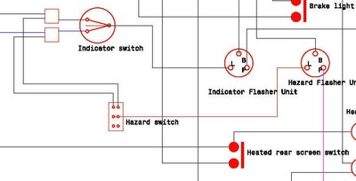
I found it eye-twisting to try follow the nice redrawn S4 wiring diagram because it is drawn mostly in wiring-loom fashion not functional fashion.
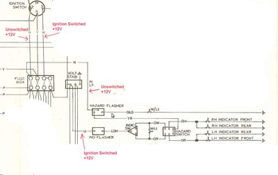
This is an extract from the S130 wiring diagram previously published here, with the irrelevant stuff blanked out to show the indicators and hazard warning circuit.
In this circuit with a double pole hazard switch, the 'back feed' through the indicators circuit is eliminated by the double pole. But in any case would not occurr unless your indicator arm switch was signalling either a right or left turn.
The following is an extract from the nice S4 wiring diagram, but I changed the colours because the greens & yellows were difficult to see. This also appears to use a double pole change-over as a Hazard switch but one position is not connected.
In this there is also no back-feed unless you are signalling left or right. But as you say a diode can be inserted into the feed to the indicator switch to prevent backflow. On a negative earth system, the positive side of the diode will be connected to the indicator flasher and the negative side to the indicator signalling switch.
The diode doesn't conduct backwards when ignition is off and hazard is on, so power rating in this state is not relevant, so the case to consider is when ignition is on and hazard is off and signalling left or right. The load under these circumstances is TWO indicator lights (Front and Rear) each 21 watts (at 12v thats 1.75 amps each), so the diode must be good for 3.5 amps plus a safety margin.
However, if you close the hazard switch with the ignition on and signalling left or right, you get an ambiguous sitiation with current flowing from both flashers to the bulbs. In the intervals when the hazard flasher is off, but the indiucator flasher is on, the indicator circuit will be driving all 4 corner lamps through the diode. So the unintentional load will be 4*21 watts or 7 amps plus a safety factor.
I would be inclined to use a diode of at least 12 amps rating and it should bbe mounted on a metal heatsink, which will need to be insulated electrically.
The diode can go in the wire from the ignition switch to the indicator flasher instead, which might be marginally better since then if the diode fails the dashboard indicator light will not flash.
Bill Williams
36/6725 S3 Coupe OGU108E Yellow over Black.
36/6725 S3 Coupe OGU108E Yellow over Black.
- billwill
- Coveted Fifth Gear

- Posts: 4417
- Joined: 19 Apr 2008
Bill Williams
36/6725 S3 Coupe OGU108E Yellow over Black.
36/6725 S3 Coupe OGU108E Yellow over Black.
- billwill
- Coveted Fifth Gear

- Posts: 4417
- Joined: 19 Apr 2008
Bill,
An eyetwistingly epic answer!
For a moment there I thought you had it all Ar5 1st, but having had 2 day to digest your post...
Diodes
Diodes are rated by their forward voltage drop - My reason for suggesting 10A was that the load (4A) is then 40% which is a rule of thumb for minimising the voltage drop.
I take your point about the unintended situation with the ignition on. As I usually indicate, pull over, and then switch the hazards on the likelihood of this situation developing is extremely high. Erratic flashing is not something I need in an emergency - Diode solution ditched!
The Switch
It hadn't clicked that the existing switch is capable of being rewired to switch off the indicator feed when the hazards are switched-on. I will see how practical this is. If it involves too much fiddling with the existing wiring I will just add a relay to do the disconnecting.
- AHM
- Coveted Fifth Gear

- Posts: 1258
- Joined: 19 Apr 2004
The last thing you want in an emergency situation is to need to think that you must stop the ignition or the normal indicators before activating the hazard lights.
Blowing the diode would turn off your hazard lights.
Think of the situation when on the motorway in fog you suddenly realise that the traffic in front of you has stopped or slowed drastically and there are big lorries coming up on your tail.
Blowing the diode would turn off your hazard lights.
Think of the situation when on the motorway in fog you suddenly realise that the traffic in front of you has stopped or slowed drastically and there are big lorries coming up on your tail.
Bill Williams
36/6725 S3 Coupe OGU108E Yellow over Black.
36/6725 S3 Coupe OGU108E Yellow over Black.
- billwill
- Coveted Fifth Gear

- Posts: 4417
- Joined: 19 Apr 2008
The Switch
It hadn't clicked that the existing switch is capable of being rewired to switch off the indicator feed when the hazards are switched-on. I will see how practical this is. If it involves too much fiddling with the existing wiring I will just add a relay to do the disconnecting.
In that S130 circuit, the actual corner indicator bulbs are wired to the centre contacts of the two pole changeover.
At rest (non-hazard), the switch blades contact the outputs if the steering column indicator switch.
In the hazard position they are swung over to the two contacts wired together which are fed from the hazard flasher, thus disconnecting the normal indicator circuit completely and instead flashing all 4 indicator lights.
{I know you probably know this. My comment is for the benefit of those who are trying to work out how that S130 circuit works}
Bill Williams
36/6725 S3 Coupe OGU108E Yellow over Black.
36/6725 S3 Coupe OGU108E Yellow over Black.
- billwill
- Coveted Fifth Gear

- Posts: 4417
- Joined: 19 Apr 2008
AHM wrote:billwill wrote:Blowing the diode would turn off your hazard lights.
You might want to think about that one again Bill!
Hmm, alright.. blowing the diode would stop your indicators working, but you probably won't notice until later.
Bill Williams
36/6725 S3 Coupe OGU108E Yellow over Black.
36/6725 S3 Coupe OGU108E Yellow over Black.
- billwill
- Coveted Fifth Gear

- Posts: 4417
- Joined: 19 Apr 2008
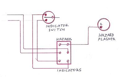
Double pole switch is best option and here's the wiring change you need based on bwill's circuit. I guess Lotus couldn't be bothered to change the loom frame and just bodged it in:
Meg
26/4088 1965 S1½ Old and scruffy but in perfect working order; the car too.
________________Put your money where your mouse is, click on "Support LotusElan.net" below.
26/4088 1965 S1½ Old and scruffy but in perfect working order; the car too.
________________Put your money where your mouse is, click on "Support LotusElan.net" below.
-

Quart Meg Miles - Coveted Fifth Gear

- Posts: 1170
- Joined: 03 Oct 2012
16 posts
• Page 1 of 2 • 1, 2
Total Online:
Users browsing this forum: No registered users and 7 guests


