71 Elan Plus 2S Tachometer Pegs at the flip of a switch!
20 posts
• Page 1 of 2 • 1, 2
Good day, Lotus Enthusiasts,
Hope you're Lotus endeavors are treating you well.
Well..I have finally finished up all the dash wiring and all controls, gauges, and lights work properly after countless manhours of punishment and troubleshooting. Oops, I mean "hobby enjoyment."
In any case, next week I would like to start buttoning things up, but still have one nagging issue. The Tachometer, Smith RVI2434/00. It reads rpms just fine during engine running. I assume the plus side of the coil is pulsing correctly. I also updated the voltage stabilizer during the dash restoration effort.
The only remaining problem is when activating an unrelated accessory, like the heater or wipers. This will cause the Tachometer needle to peg full scale past "8000 rpm" and stays there. Once you turn the key to off, the needle resets back down to "0".
I've checked all connections, as well as the Yellow/White" wire loop behind the tach. All grounds appear secure and there are no other issues noted anywhere in the instrumentation, or wiring. All other dash components function well and read correctly.
Should I start to assume its the Tach itself? Why would flipping a rocker switch on the heater fan, or wipers, or other switch, send my Tach overboard, and peg the needle? (It is not consistent, sometimes it performs without issue when you flip a switch or turn on something else. )
Anyone in the Lotus community see this type of thing before? Any troubleshooting suggestions are appreciated!
Thanks !
Mike
'71 Lotus Elan Plus 2S130 (Type 50/0179)
'70 Opel GT
'67 Sunbeam Alpine
'88 Porsche 924 S
'67 Elan S3 DHC
'70 Opel GT
'67 Sunbeam Alpine
'88 Porsche 924 S
'67 Elan S3 DHC
- mjbeanie
- Second Gear

- Posts: 151
- Joined: 29 Mar 2019
Mike,
A lot of electronic circuits are susceptible to power-line noise. Switching on / off a device connected to the same supply can cause the voltage to the tach to momentarily drop or to spike, this is particularly the case for rotating machinery (wiper / heater for example) where the switch-on current can be many times the steady state draw.
Having said that, the electronics in the RVI tach (of which there are two types) are so basic, its not clear to me how a spike or dip would cause the circuitry to latch and give the symptoms you describe. The Spyda module (a modern replacement for the electronics) did suffer from this under certain circumstances, but unless your tach has been updated, that shouldn't be a problem.
There are a couple of electrolytic caps in the tach circuitry which will be on their way to age related failure, and they could cause erratic behaviour, and replacing them may be the answer. There are many youtube videos of how to rebuild the electronics in an RVI tach, no real electronic skills are needed except for knowing which end of a soldering iron to hold. Speedycables in the UK will rebuild the tach for you, and although I mentioned the Spyda module could exhibit your symptoms, that is only in very rare cases - otherwise its a good fix.
Good luck.
68 Elan S3 HSCC Roadsports spec
71 Elan Sprint (still being restored)
32 Standard 12
Various modern stuff
71 Elan Sprint (still being restored)
32 Standard 12
Various modern stuff
- Andy8421
- Coveted Fifth Gear

- Posts: 1224
- Joined: 27 Mar 2011
This takes me back to similar I had with an RVI on an MGB. After much scratching heads, someone came up with a dodgy park switch in my wiper motor.
It may be totally unrelated to your issue, indeed I hope it is, but just in case...might be worth a check.
It may be totally unrelated to your issue, indeed I hope it is, but just in case...might be worth a check.
Hal Adams
Evora SR
Elan +2
Evora SR
Elan +2
-

HCA - Coveted Fifth Gear

- Posts: 1087
- Joined: 03 Jan 2020
Thanks guys
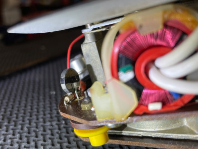
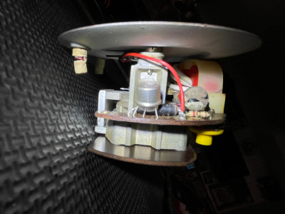
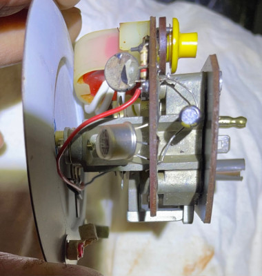
Andy I've decided to try the cap replacement. I've disassembled the unit. I will look on youtube for some additional guidance. I did want to show you the circuit board. I am not sure how to determine the value for the cap (s). I assume the circular striped component (black/white stripes) is a resistor? While I can use a soldering iron, I am not a wiz on vintage electronics. Any insight into what I am looking at and next steps would be appreciated. Thanks. MIke
Andy I've decided to try the cap replacement. I've disassembled the unit. I will look on youtube for some additional guidance. I did want to show you the circuit board. I am not sure how to determine the value for the cap (s). I assume the circular striped component (black/white stripes) is a resistor? While I can use a soldering iron, I am not a wiz on vintage electronics. Any insight into what I am looking at and next steps would be appreciated. Thanks. MIke
'71 Lotus Elan Plus 2S130 (Type 50/0179)
'70 Opel GT
'67 Sunbeam Alpine
'88 Porsche 924 S
'67 Elan S3 DHC
'70 Opel GT
'67 Sunbeam Alpine
'88 Porsche 924 S
'67 Elan S3 DHC
- mjbeanie
- Second Gear

- Posts: 151
- Joined: 29 Mar 2019
Hi
The item with the black and white stripes is a thermistor - a resistor who's value varies according to temperature.
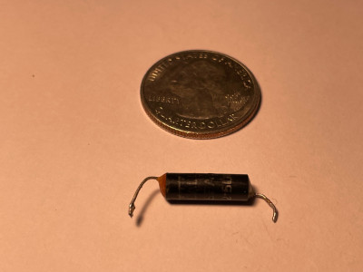
The capacitor is the black cylinder lying on the board. Looking round the internet it seems the value is 2uF - the value is usually written on electrolytic capacitors so you wont have the decode coloured stripes. When buying a replacement make sure you get a working voltage of 16V or more. When replacing be aware that they are polarity conscious - ie note which end is positive (+) when you take the old one out and make sure you put in the new one the same way round.
HTH
Baggy
- Baggy2
- Third Gear

- Posts: 267
- Joined: 05 Feb 2010
Thanks so much HTH. I appreciate the insight, feedback and recommendations.
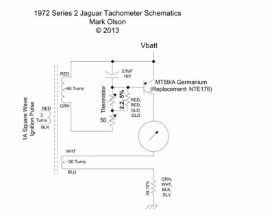
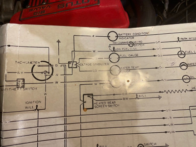
During some internet surfing on Tachs, I found this little tidbi for a "GEN 2 Smiths Tachometer" used in the 60's-70's.
It may help other troubleshooters regarding general circuit description of similar vintage gauges.
During some internet surfing on Tachs, I found this little tidbi for a "GEN 2 Smiths Tachometer" used in the 60's-70's.
It may help other troubleshooters regarding general circuit description of similar vintage gauges.
'71 Lotus Elan Plus 2S130 (Type 50/0179)
'70 Opel GT
'67 Sunbeam Alpine
'88 Porsche 924 S
'67 Elan S3 DHC
'70 Opel GT
'67 Sunbeam Alpine
'88 Porsche 924 S
'67 Elan S3 DHC
- mjbeanie
- Second Gear

- Posts: 151
- Joined: 29 Mar 2019
There are two different circuits for the RVI tacho, that diagram might not be the right one.
Thay have been posted on this forum at least once, possibly more times.
See topic: viewtopic.php?f=39&t=49622&hilit=+tacho
Thay have been posted on this forum at least once, possibly more times.
See topic: viewtopic.php?f=39&t=49622&hilit=+tacho
Bill Williams
36/6725 S3 Coupe OGU108E Yellow over Black.
36/6725 S3 Coupe OGU108E Yellow over Black.
- billwill
- Coveted Fifth Gear

- Posts: 4417
- Joined: 19 Apr 2008
Thank you all. I have retracted the aforementioned 2.5uf Capacitor. The value has been confirmed upon examination of the old component. The next hurdle seems to be finding one. That capacitance value appears uncommon. I have reached out to Mouser electronics.
However I have found 2.2 uf and 2.7 uf in aluminum electrolytic. Will either of those work?
But no luck finding a 2.5uf. Any suggestions are appreciated. Thanks for the continued support on this effort.
I would like to try this cap replacement before moving toward the RVC conversion route via Spyda components.
'71 Lotus Elan Plus 2S130 (Type 50/0179)
'70 Opel GT
'67 Sunbeam Alpine
'88 Porsche 924 S
'67 Elan S3 DHC
'70 Opel GT
'67 Sunbeam Alpine
'88 Porsche 924 S
'67 Elan S3 DHC
- mjbeanie
- Second Gear

- Posts: 151
- Joined: 29 Mar 2019
Go with the 2.2 microfarad. make sure it is at least 16V. Higher is fine, but it will be dimensionally bigger if you up the voltage too far.
If that fixes it, the tach will need to be calibrated, there are videos on youtube about how to do that. It is very straightforward - but don't expect miracles, these aren't precision instruments.
Make sure you put the cap in the right way around, polarity matters for electrolytics.
Given your new found enthusiasm for vintage electronics, if the cap doesn't fix it, it wouldn't take much to replace the other components. I order of likely impact, I would sequence it cap (which you are doing), transistor, the resistors (the variable resistor first) then finally the thermistor.
This kind gentleman has posted a description of how it all works. Its a subtle design, depending a lot on the magnetic characteristics of the pulse transformer.
http://www.mgb-stuff.org.uk/harvit.htm
Good luck.
68 Elan S3 HSCC Roadsports spec
71 Elan Sprint (still being restored)
32 Standard 12
Various modern stuff
71 Elan Sprint (still being restored)
32 Standard 12
Various modern stuff
- Andy8421
- Coveted Fifth Gear

- Posts: 1224
- Joined: 27 Mar 2011
Just wanted to say thanks to all for the help on this one. What a great group of Elan folks! Got a fresh 2.2 microfarad, 50V cap (audio quality lol) for a few bucks, and installed it yesterday.
Placed it back in the dash after cleaning up all connections and it now reads rock steady. Also ran a fresh singular ground wire to the case. NO fluctuations or pegging noted! I can turn the heater on, the wipers on, and the needle will not move. This is a great easy fix which might save others some big $, when the tach goes south. It is certainly worth an hour and a couple bucks to try it! Even the RPM's seem spot on. No need to chase this further. YAY!
Interestingly this tach effort introduced another problem however-
My red ignition light stays on all the time, where it was operating normally before. Ugh! I measured 14.2 VDC, at the battery which matches the battery gauge. The wiring looks in order. Not sure where the problem lies. The starting/ charging circuit appears in full working order. Why is the darn light now on?? Any troubleshooting suggestions always welcome! One step forward-two steps back. Good grief!
Here is the new electrolytic capacitor installed. I placed it on the underside of the circuit board toward the back of the case.
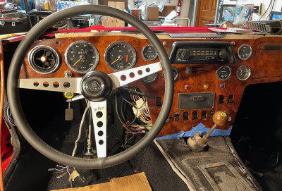
Also included an updated photo of the interior, as I just finished installing center console and shift boot, securing dashboard, lettering, and crash pad install.
'71 Lotus Elan Plus 2S130 (Type 50/0179)
'70 Opel GT
'67 Sunbeam Alpine
'88 Porsche 924 S
'67 Elan S3 DHC
'70 Opel GT
'67 Sunbeam Alpine
'88 Porsche 924 S
'67 Elan S3 DHC
- mjbeanie
- Second Gear

- Posts: 151
- Joined: 29 Mar 2019
Glad the tach works.
The wiring is really tight behind the dash, are you sure you didn’t disconnect or disturb anything connected to the ign warning light?
Unlike the other panel / warning lights, the ign warning light it isn’t earthed. Have you changed any wiring with your additional earth ?
The wiring is really tight behind the dash, are you sure you didn’t disconnect or disturb anything connected to the ign warning light?
Unlike the other panel / warning lights, the ign warning light it isn’t earthed. Have you changed any wiring with your additional earth ?
68 Elan S3 HSCC Roadsports spec
71 Elan Sprint (still being restored)
32 Standard 12
Various modern stuff
71 Elan Sprint (still being restored)
32 Standard 12
Various modern stuff
- Andy8421
- Coveted Fifth Gear

- Posts: 1224
- Joined: 27 Mar 2011
Gosh, I went over it again. I see nothing abnormal. In addition this light connections are really isolated. I chased teh continuity back to the alternator, cleaned up the alternator and ground connections. No joy.
The light has one direct brown/yellow wire to the alternator. Other lead goes to the voltage stabilizer terminal where the tach connects as well. No issues noted. When you turn the key to prepare for start the light is bright. At idle the light is half dim. Maybe the refurbished tach is powering it somehow? But it is still frustrating.
The dash is fully installed and the other 99% is operating perfectly. I can see all the wiring associated with the ignition light, so I am reluctant to remove the dash. Its is all buttoned up now.
I may just call this good, and if this continues, I will perhaps disconnect the light. The voltmeter will suffice as an indication of the charge system health. And as mentioned getting 14+ Volts at the battery.
Too many man hours on this one. I usually don't stop until its 100% but given the scope of this dash effort I may just workaround this one. Thanks Andy, for your help!!
'71 Lotus Elan Plus 2S130 (Type 50/0179)
'70 Opel GT
'67 Sunbeam Alpine
'88 Porsche 924 S
'67 Elan S3 DHC
'70 Opel GT
'67 Sunbeam Alpine
'88 Porsche 924 S
'67 Elan S3 DHC
- mjbeanie
- Second Gear

- Posts: 151
- Joined: 29 Mar 2019
Everybody calls that the ignition warning light, but it's really the exicter voltage supply circuit to the alternator. It comes on when you turn the key because the voltage on one side of the light is higher than the other. It goes out when the voltage on both sides is the same.
You dont have the wire going from the tach to the instrument voltage regulator on the 10V regulated tab do you?
You dont have the wire going from the tach to the instrument voltage regulator on the 10V regulated tab do you?
Bud
1970 +2S Fed 0053N
"Winnemucca - says it all really!!"
1970 +2S Fed 0053N
"Winnemucca - says it all really!!"
- Bud English
- Fourth Gear

- Posts: 942
- Joined: 05 Nov 2011
Hello Bud,
I don't think so, I followed the previous wiring and schematic closely. The spade connectors are idiot proofed as well, regarding the male and female on the harness and stabilizer. Basically the hot lead for the tach, ignition light, battery gauge and low fuel warning all connect to the same lugs on the stabilizer. I may doublecheck the stabilizer case ground again.
However, you raised the point that the light would go out when the charging reached a steady state with equal voltages on both sides.
"It comes on when you turn the key because the voltage on one side of the light is higher than the other. It goes out when the voltage on both sides is the same"
My battery is in good shape but shows as charging at about 13V at the battery gauge. Could it be that the light will go out when the battery doesn't need a charge and the indicator reads at the middle at 12V?
(However, It did not behave this way in weeks prior to my tach adventure.)
'71 Lotus Elan Plus 2S130 (Type 50/0179)
'70 Opel GT
'67 Sunbeam Alpine
'88 Porsche 924 S
'67 Elan S3 DHC
'70 Opel GT
'67 Sunbeam Alpine
'88 Porsche 924 S
'67 Elan S3 DHC
- mjbeanie
- Second Gear

- Posts: 151
- Joined: 29 Mar 2019
20 posts
• Page 1 of 2 • 1, 2
Total Online:
Users browsing this forum: No registered users and 14 guests

