Voltage Regulator Reconfigured for Alternator
18 posts
• Page 1 of 2 • 1, 2
Please bear with me if the pictures don’t work - my first time posting pictures.
I’m installing an alternator on my 71 Elan Sprint. I’ve searched all these forums and ended up (almost) as confused as when I started.
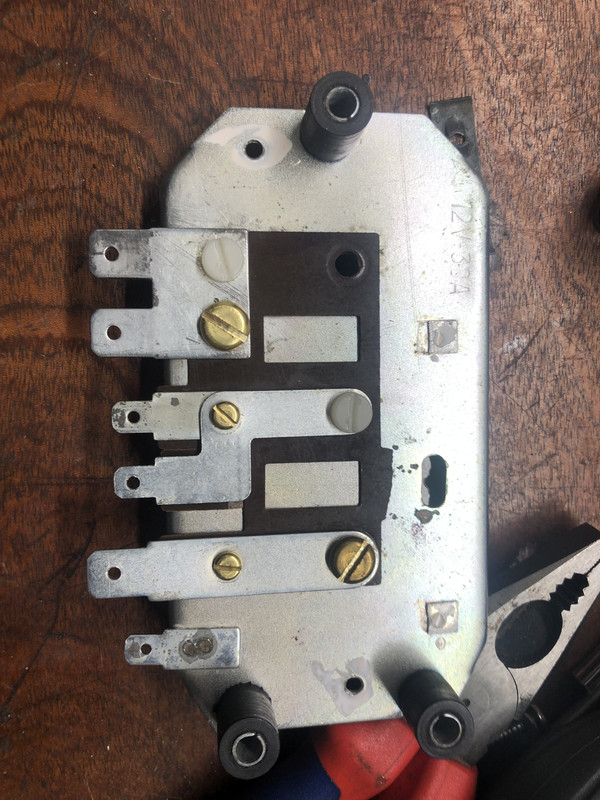
I want to retain the voltage regulator for the sake of appearance and tidy wires. I’ve ‘gutted’ the control box and reconfigured the various strips. This involved enlarging some holes on the backplate and using some Bakelite washers to retain insulation where required.
Also used some nylon bolts to fix the various strips. I have installed a 40 amp fuse between the power feed from the solenoid and the alternator input and feeds to the other circuits.
I may have this completely wrong so please let me know!
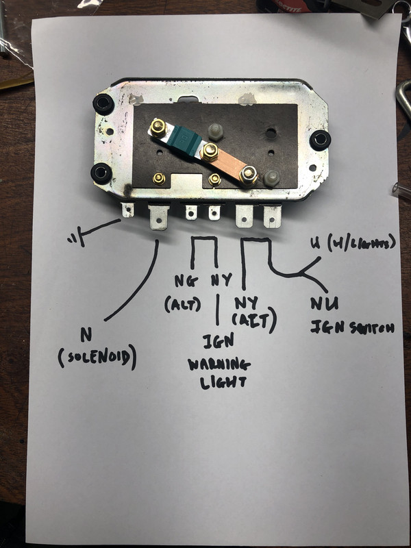


71 Elan Sprint FHC Pistachio
36/0262E
36/0262E
- Bodmin
- Second Gear

- Posts: 51
- Joined: 19 Jan 2022
It is difficult to see from the pictures what is insulated from the metal frame, and what isn't. Assuming everything is insulated from the metal frame, then it should work.
However, your placement of the fuse isn't ideal. While it does protect the cable from the solenoid to the control box, it doesn't do much else. When the engine is running, (depending on the model of alternator you have chosen) the alternator output is capable of frying the downstream cables.
It is better than nothing (and better than the original).
68 Elan S3 HSCC Roadsports spec
71 Elan Sprint (still being restored)
32 Standard 12
Various modern stuff
71 Elan Sprint (still being restored)
32 Standard 12
Various modern stuff
- Andy8421
- Coveted Fifth Gear

- Posts: 1222
- Joined: 27 Mar 2011
Andy8421 wrote:It is difficult to see from the pictures what is insulated from the metal frame, and what isn't. Assuming everything is insulated from the metal frame, then it should work.
However, your placement of the fuse isn't ideal. While it does protect the cable from the solenoid to the control box, it doesn't do much else. When the engine is running, (depending on the model of alternator you have chosen) the alternator output is capable of frying the downstream cables.
It is better than nothing (and better than the original).
Many thanks. That is exactly the information I needed.
You are correct, everything is insulated from the back plate. I have a second sacrificial voltage regulator so used spare mica washers between the mica sheets.
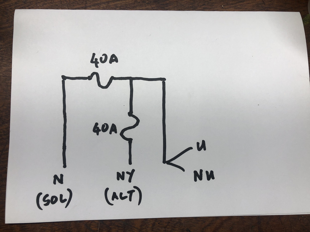
It sounds like I need two fuses within the box. One on the feed from the solenoid which I’m keen to keep, and the second on the alternator feed. This shouldn’t be too difficult given the parts from the spare voltage regulator, and some additional copper strip.
Interestingly I haven’t seen twin fuses used on any of the forum inputs relating to this subject. Sketch of proposal attached.
71 Elan Sprint FHC Pistachio
36/0262E
36/0262E
- Bodmin
- Second Gear

- Posts: 51
- Joined: 19 Jan 2022
Fusing is a complicated subject, what you are protecting and why all drive the fuse size and type.
In your case, I would be inclined to separate the alternator fuse from the main wiring fuse (you have them in series) and use a bigger fuse for the alternator.
Rotating electrical machinery does all sorts of weird things, and it is possible you could generate a transient current spike that would be sufficient to blow a 40A fuse. 2x the rated output of the alternator might be a good place to start.
As an example, My Wife's Merc SUV has a 170A fuse on the alternator circuit.
68 Elan S3 HSCC Roadsports spec
71 Elan Sprint (still being restored)
32 Standard 12
Various modern stuff
71 Elan Sprint (still being restored)
32 Standard 12
Various modern stuff
- Andy8421
- Coveted Fifth Gear

- Posts: 1222
- Joined: 27 Mar 2011
It common on alternators to insert a fusable link wire rather than a fuse, often used by OEMs. I added one when I changed to a small higher output alternator as extra safety measure.
'73 +2 130/5 RHD, now on the road and very slowly rolling though a "restoration"
- mbell
- Coveted Fifth Gear

- Posts: 2643
- Joined: 07 Jun 2013
The picture is typical of current vehicle practice. The pre-fuse box is either mounted directly on the battery terminal, or connected via a short length of high current cable. The box has a number of high current fuses, each feeding a separate fuse box around the car. One fuse is for the connection to the alternator.
68 Elan S3 HSCC Roadsports spec
71 Elan Sprint (still being restored)
32 Standard 12
Various modern stuff
71 Elan Sprint (still being restored)
32 Standard 12
Various modern stuff
- Andy8421
- Coveted Fifth Gear

- Posts: 1222
- Joined: 27 Mar 2011
Andy8421 wrote:
In your case, I would be inclined to separate the alternator fuse from the main wiring fuse (you have them in series) and use a bigger fuse for the alternator.
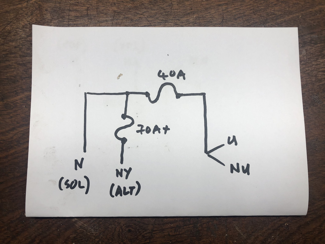
Thanks again for your input. If you can indulge me a little longer, when you say I have the fuses in series I assume this means the two fuses running between the alternator output and the solenoid? That being the case is the diagram I have attached here a better fit for connecting the alternator?
Appreciate the full bells & whistles fuse box you have shown on your latest post, but at the moment I don’t want to go to that extent. I just want to wire in the alternator without blowing up either the car or myself!
71 Elan Sprint FHC Pistachio
36/0262E
36/0262E
- Bodmin
- Second Gear

- Posts: 51
- Joined: 19 Jan 2022
What i did, a few years ago. Not sure if part number is still good.
Can only find first picture, I drilled out rivets and fitted new regulator
Can only find first picture, I drilled out rivets and fitted new regulator
Born, and brought home from the hospital (no seat belt (wtf)) in a baby!
Find out where the limits are, and start from there
Love your Mother
Earth
Find out where the limits are, and start from there
Love your Mother
Earth
-

h20hamelan - Coveted Fifth Gear

- Posts: 1962
- Joined: 25 Sep 2010
h20hamelan wrote:What i did, a few years ago. Not sure if part number is still good.
Can only find first picture, I drilled out rivets and fitted new regulator
Nice hardware there! Were you fitting an alternator? If so do you have any wiring diagrams, and how did you configure the fuses?
71 Elan Sprint FHC Pistachio
36/0262E
36/0262E
- Bodmin
- Second Gear

- Posts: 51
- Joined: 19 Jan 2022
not sure I recall exactly, it seemed easy at the time 10 or so years ago.
Yes, alternator. I know there was a bit of soldering involved.
Yes, alternator. I know there was a bit of soldering involved.
Born, and brought home from the hospital (no seat belt (wtf)) in a baby!
Find out where the limits are, and start from there
Love your Mother
Earth
Find out where the limits are, and start from there
Love your Mother
Earth
-

h20hamelan - Coveted Fifth Gear

- Posts: 1962
- Joined: 25 Sep 2010
Your last circuit where the alternator is connected before the main fuse is a satisfactory way to one which includes a primary fuse.
Fuses are used to protect the wiring NOT the device connected to it. A separate alternator fuse will protect the wiring in the case of perhaps a device dead short, at this point the alternator is probably U/S anyway.
Fuses are used to protect the wiring NOT the device connected to it. A separate alternator fuse will protect the wiring in the case of perhaps a device dead short, at this point the alternator is probably U/S anyway.
- Craven
- Coveted Fifth Gear

- Posts: 1623
- Joined: 14 Sep 2013
Craven wrote:Your last circuit where the alternator is connected before the main fuse is a satisfactory way to one which includes a primary fuse.
Fuses are used to protect the wiring NOT the device connected to it. A separate alternator fuse will protect the wiring in the case of perhaps a device dead short, at this point the alternator is probably U/S anyway.
Agreed.
My point of including the picture of a 'pre-fuse' box was to illustrate that modern practice is to fuse alternators and high current downstream wiring, and to have these fuses at the point of power distribution. As Craven points out, this is to protect the wiring, not the end device.
You final diagram will work, it is much better that the original diagram, and in its own way mimics the function of a modern 'pre-fuse' box. If it is good enough for Mercedes Benz......
68 Elan S3 HSCC Roadsports spec
71 Elan Sprint (still being restored)
32 Standard 12
Various modern stuff
71 Elan Sprint (still being restored)
32 Standard 12
Various modern stuff
- Andy8421
- Coveted Fifth Gear

- Posts: 1222
- Joined: 27 Mar 2011
What you need to do to remove this worry of high current and voltage spikes it to fit a dc generator and control box. Just like they did originally in the 60's. 
- Keith Scarfe
- Second Gear

- Posts: 219
- Joined: 10 May 2004
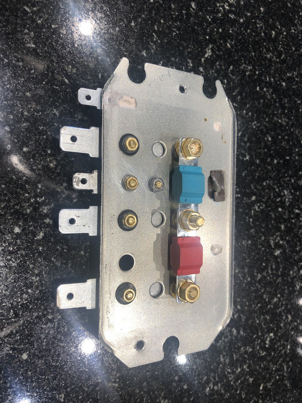
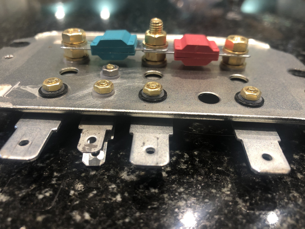
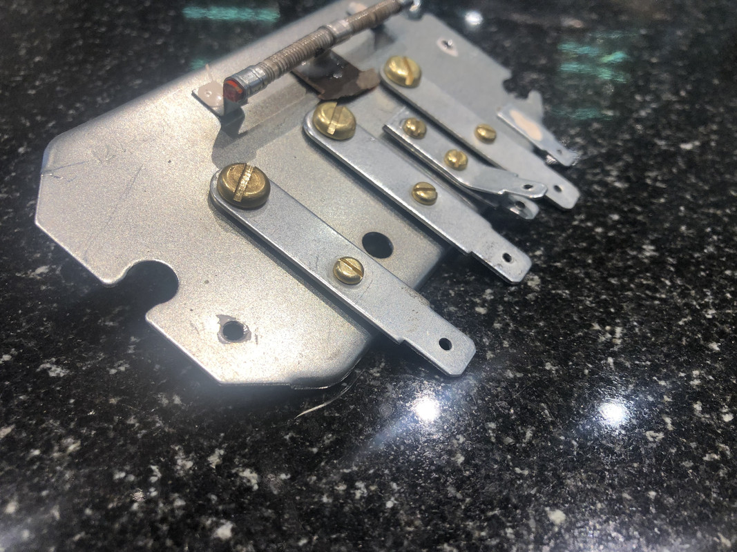
For the record final configuration as per pictures. All the strips are insulated relative to the metal board using plastic washers giving 2-3mm stand off. Fortunately I had a couple of old regulators which allowed me 3 independent strips with 8mm blade connectors.
Holes in existing backplate are 30mm apart making the two fuses an easy install.
Tabs on extreme left & right are for alternator feed and solenoid. Centre tab is for Blue & Blue/Yellow feeding vehicle electrical system.
The 6.3mm tabs are connected for ignition warning light & alternator.

Holes in existing backplate are 30mm apart making the two fuses an easy install.
Tabs on extreme left & right are for alternator feed and solenoid. Centre tab is for Blue & Blue/Yellow feeding vehicle electrical system.
The 6.3mm tabs are connected for ignition warning light & alternator.


71 Elan Sprint FHC Pistachio
36/0262E
36/0262E
- Bodmin
- Second Gear

- Posts: 51
- Joined: 19 Jan 2022
18 posts
• Page 1 of 2 • 1, 2
Total Online:
Users browsing this forum: No registered users and 13 guests


