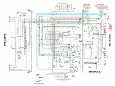
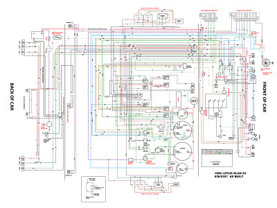
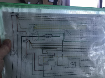
New wiring diagram for peer review
28 posts
• Page 1 of 2 • 1, 2
Hello All,
I am working on establishing a new wiring diagram for my '66 Elan S3 Pre-Airflow FHC and would like to have those folks on this board with more experience in such matters to review my diagram. A few things to take into consideration are: this is a USA car in the midwest where temps get warm, so I am adding an auxiliary cooling fan kit from Revotec. This is not going to be a historically accurate car. This is to be a road driven car. I am adding fused circuits and some relays for modern safety of wiring. I am running LED turn signals, sidelights, brake lights. I will have halogen headlights. I am adding a hazard light switch circuit. I am adding a "CHMSL" (third brake light) which is also LED. I am converting the car to negative ground and have purchased an alternator and modern starter with built in solenoid from RD. I will be eliminating the firewall mounted starter solenoid. I am not going to have headlight flashing, or microswitch control of headlights. The fuse blocks shown in the diagram are from Blue Sea which is a supplier for marine wiring devices. I plan to put them in the engine bay near the pedal box.
I think that one of the best things I can do for any future owner down the road is provide them with an accurate diagram. This also helps me wrap my head around the process of building the new loom. ( Actually, I will be modifying a new harness I purchased from Kelvedon before I install it in the car.)
I look forward to hearing constructive feedback from the group. No haters please.
Kind regards,
Eric Johnson
Life's too short to drive boring cars!
'66 S3 Elan Coupe'
'66 S3 Elan Coupe'
- Bushwacker
- First Gear

- Posts: 28
- Joined: 20 Jul 2012
Resolution of diagram available to me precludes detail conformation but it seems you are adding to the incorrect diagram for a 66 car. You will need many more to bring a basically the S2 wired car up to your diagram, for instance, 66 car will not have the two headlight/dip relays as shown.
FWIW.
FWIW.
- Craven
- Coveted Fifth Gear

- Posts: 1622
- Joined: 14 Sep 2013
I feel sorry for all the Phantasians who need wiring diagrams laid out exactly like the wiring harness, it makes the diagram very difficult to follow and to find wiring errors or later problems.
As an Aphantasian I find a logical diagram (such as that which was issued by Lotus for the S1 and S2 Elans) much, much easier to understand and to use to fix problems.
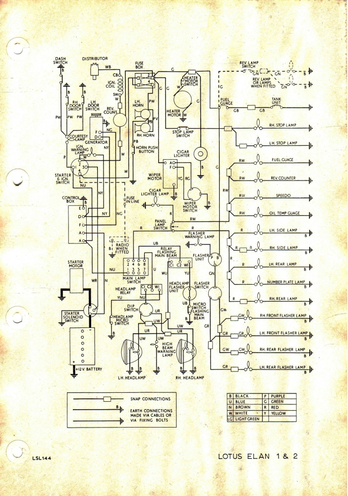
As an Aphantasian I find a logical diagram (such as that which was issued by Lotus for the S1 and S2 Elans) much, much easier to understand and to use to fix problems.

Bill Williams
36/6725 S3 Coupe OGU108E Yellow over Black.
36/6725 S3 Coupe OGU108E Yellow over Black.
- billwill
- Coveted Fifth Gear

- Posts: 4417
- Joined: 19 Apr 2008
Hello Bill,
Yes, I agree, the diagram for the S1 & 2 is much easier to read and visualize. I have the 1971 Workshop Manual which has diagrams for all series cars. I just decided to start with the S3 one that I had already scanned into Photoshop to start reworking.
I'm not as concerned about how it looks as I am about the functionality of the end product. I can always go back and try to illustrate a more sensible and clear version for final.
Thanks,
Eric
Life's too short to drive boring cars!
'66 S3 Elan Coupe'
'66 S3 Elan Coupe'
- Bushwacker
- First Gear

- Posts: 28
- Joined: 20 Jul 2012
Here is a slightly larger file, if that helps.
Eric
Eric
Life's too short to drive boring cars!
'66 S3 Elan Coupe'
'66 S3 Elan Coupe'
- Bushwacker
- First Gear

- Posts: 28
- Joined: 20 Jul 2012
Bushwacker wrote:Hello Bill,
Yes, I agree, the diagram for the S1 & 2 is much easier to read and visualize. I have the 1971 Workshop Manual which has diagrams for all series cars. I just decided to start with the S3 one that I had already scanned into Photoshop to start reworking.
I'm not as concerned about how it looks as I am about the functionality of the end product. I can always go back and try to illustrate a more sensible and clear version for final.
Thanks,
Eric
I don't visualise anything at all.
Bill Williams
36/6725 S3 Coupe OGU108E Yellow over Black.
36/6725 S3 Coupe OGU108E Yellow over Black.
- billwill
- Coveted Fifth Gear

- Posts: 4417
- Joined: 19 Apr 2008
Eric,
The wiring diagram looks very good. Just a few comments - in the spirit of simplifying and adding lightness:
Unless the inertia switch can't cope, the fuel pump relay and fused supply to the relay could be ditched, Facet pumps draw less than 2 amps. Just drive it directly from the inertia switch.
The fuses in the two supply wires from the starter solonoid to the fuse banks may be unnecessary depending on the sum of the fuse ratings in the banks. If the sum of the fuse ratings is less than the rating of the supply wire, then the extra fuses aren't required.
The hazard warning wiring doesn't seem to be complete.
There has been a discussion thread whether it is worth putting relays into the window motor circuits. Your circuit seems correct, but if the original switches can carry the current OK, 4 relays and associated wiring is quite an overhead.
Andy.
68 Elan S3 HSCC Roadsports spec
71 Elan Sprint (still being restored)
32 Standard 12
Various modern stuff
71 Elan Sprint (still being restored)
32 Standard 12
Various modern stuff
- Andy8421
- Coveted Fifth Gear

- Posts: 1220
- Joined: 27 Mar 2011
Hello Andy,
Thanks for those bits of wisdom.
Yes, I see that I had forgotten to add the Green/Red and Green/White wires from the hazard switch to the indicator switch.
Regarding the window switching. How do I determine if the window switches can handle the current required for the window motors?
I was wondering about the whole relay idea for the fuel pump, since the Facet pumps draw so little power. Thanks for that.
I was wondering if for the power feed to my "always hot" fuse block, could that just come directly from the alternator instead of passing through the starter solenoid? That seems to be just a connection point in my mind.
Cheers!
Life's too short to drive boring cars!
'66 S3 Elan Coupe'
'66 S3 Elan Coupe'
- Bushwacker
- First Gear

- Posts: 28
- Joined: 20 Jul 2012
Comments below in italics.
Regarding the window switching. How do I determine if the window switches can handle the current required for the window motors? Arguably the switches were designed to take the load. Having said that, my own view is the wiring on the Elan is poorly designed, badly fused, and under-specced in many areas. There are few Sprints on the road where one or more connections in the white multiplug under the dash haven't melted. My window motors are a bit asthmatic, but I don't think it is the switches. Search for the tread on the subject, there was some useful info there. I haven't seen a failed switch, or a thread about one, so my guess is that they are adequate.
I was wondering about the whole relay idea for the fuel pump, since the Facet pumps draw so little power. Thanks for that. Do check the inertia switch. If it was designed for a car with an ECU, it is possible it was only designed for low current.
I was wondering if for the power feed to my "always hot" fuse block, could that just come directly from the alternator instead of passing through the starter solenoid? That seems to be just a connection point in my mind. It is good practice to distribute power from a single point - the starter solonoid (relay really) is a good place to do this. It is also pretty hostile down the back of the alternator, I wouldn't want to have a junction and a separate feed coming from there.
Hope this helped.
Andy.
68 Elan S3 HSCC Roadsports spec
71 Elan Sprint (still being restored)
32 Standard 12
Various modern stuff
71 Elan Sprint (still being restored)
32 Standard 12
Various modern stuff
- Andy8421
- Coveted Fifth Gear

- Posts: 1220
- Joined: 27 Mar 2011
Eric,
That's a really useful diagram, thank you for posting it. I'm planning a rewire of my S4 which will incorporate many of the same features in particular more fuses and relays and a general tidy up of the wiring.
Would it be possible please to post your diagram in it's native file format rather than as a picture as it could then be printed in a larger format with clarity. Even the second image you posted is a challenge to read when printed at A4 and my eyes need a minimum of A3 to be workable these days!
Thank you.
- Elanman68
- Second Gear

- Posts: 113
- Joined: 07 May 2015
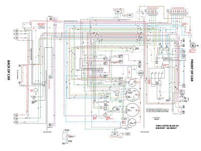
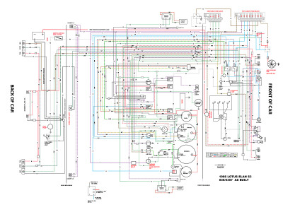
Hello All,
I have made a few alterations and updates to my wiring diagram to run by everyone. I will also attempt to upload the file so that you can more easily see it. It should be 16 x 20 inches @150dpi.
Please advise me on how to load a file in another way if this isn't giving it to you bigger.
I have decided to simplify the window switch wiring back to original. Note that my switches are located in the doors as this is an early 66 coupe.
I was thinking about taking the white heavy feed wire from the ignition switch to the "switched power" fuse block and run through a relay for this power. Seems like a good use for the relay idea. So lower power through the ignition switch to the relay, then it brings in a 20 amp feed from the "hot" fuse block. Does this sound like a good idea?
Have a look around at it and let me know your thoughts.
Much appreciated.
Eric
Life's too short to drive boring cars!
'66 S3 Elan Coupe'
'66 S3 Elan Coupe'
- Bushwacker
- First Gear

- Posts: 28
- Joined: 20 Jul 2012
Sorry about the small image size folks.
Let's see if this one is better.
Eric
Let's see if this one is better.
Eric
Life's too short to drive boring cars!
'66 S3 Elan Coupe'
'66 S3 Elan Coupe'
- Bushwacker
- First Gear

- Posts: 28
- Joined: 20 Jul 2012
Bushwacker wrote: I have made a few alterations and updates to my wiring diagram to run by everyone. I will also attempt to upload the file so that you can more easily see it. It should be 16 x 20 inches @150dpi.
Please advise me on how to load a file in another way if this isn't giving it to you bigger
Eric,
I don't know what the original format of your diagram is? I know that PDFs can be uploaded as attachments to posts rather than images and there are some examples of this elsewhere in the electrical section of the site. A printed 16 x 20 inches would be perfect for working from.
Thank you.
- Elanman68
- Second Gear

- Posts: 113
- Joined: 07 May 2015
Don't be 'taken-in' by the size & detail of a picture displayed in a message, that is NOT the uploaded level of detail, the forum software reduces the resolution to create a posted message,
Right-button click on the picture and choose the option "Open in another tab" or a similar such choice (it varies from one browser program to another). The picture should then open in a new tab at the original resolution. To view on screen you can usually magnify by pressing CTRL together with the plus key and then move around the document with the arrow keys. {you can reduce it again with CTRL and the MINUS key} Where the keyboard has a number pad use the PLUS and MINUS keys of the number pad. For Apple computers use the keys on the top row.
To get large printouts will depend on your printer-driver software. Most of the drivers have a SCALE facility which you can try, though some of those will not actually print (on extra sheets) those parts of the diagram which overflow the page size. If that is the case you will need to use a photo/graphics manipulation program to cut the picture into different files that fit one page of your printer.
Bill Williams
36/6725 S3 Coupe OGU108E Yellow over Black.
36/6725 S3 Coupe OGU108E Yellow over Black.
- billwill
- Coveted Fifth Gear

- Posts: 4417
- Joined: 19 Apr 2008
Agreed, you probably dont need high resolution.
If you open in a new tab, enlarge your viewing screen. Then take screenshots of 1/4 of the screen at a time. Then cut and paste together your colour diagram in the ziplock with the desiccant, add to your tool kit in the boot.
If you open in a new tab, enlarge your viewing screen. Then take screenshots of 1/4 of the screen at a time. Then cut and paste together your colour diagram in the ziplock with the desiccant, add to your tool kit in the boot.
Born, and brought home from the hospital (no seat belt (wtf)) in a baby!
Find out where the limits are, and start from there
Love your Mother
Earth
Find out where the limits are, and start from there
Love your Mother
Earth
-

h20hamelan - Coveted Fifth Gear

- Posts: 1957
- Joined: 25 Sep 2010
28 posts
• Page 1 of 2 • 1, 2
Total Online:
Users browsing this forum: No registered users and 17 guests

