Nose cone wiring tidy up
40 posts
• Page 1 of 3 • 1, 2, 3
Hi
I'm going through the nose cone putting relays on all the high current devices - horn, main beam, dip, fog, cooling fan. I had previously put relays on the lights but wasn't happy with having them situated deep in the nose, inaccessible unless the grille is removed, and a bit tricky to reach even then. Also, concerned about corrosion in the connectors.
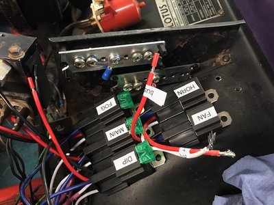
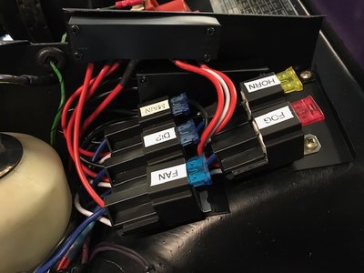
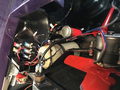
I've decided to place them where the horn relay is, swapping out the fat Lucas relay and moving the solenoid valve to a better spot on the radiator mount. I can just about fit all five fused relays there. The wiring scheme is simple - use the original switched feeds as relay triggers and lay new ground and +12v direct from the battery terminal on the starter terminal to the hot side of each of the relays, but there is a problem. I do not want a connector with five wires branching out to feed the relays as it looks a bit crap and it's unreliable, so thought some sort of bus bar would do the trick.
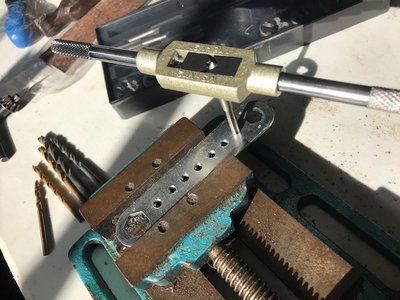
Checking eBay turned up some candidates but they were all a bit expensive, so I decided to make my own from a scrap of metal.
I do love my tap & die set. Cannot imagine how I managed before I bought it.
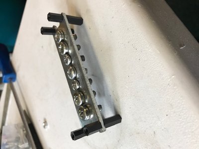
I made another bar for the grounds and fitted them to the bracket that prevents intake air getting round the radiator.
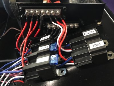
The +12v bar is at the top and will have an insulating shroud to protect it from accidental shorts (eventually). I'm hoping the tails from the relay connectors can be screwed directly onto the bars; this will give a neat, professional appearance.
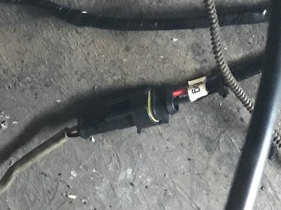
I bought some interesting connectors for joining the relays to the loom. They are crimp type but have heat shrink sleeves and on heating will give a waterproof seal. You can see some of them in this picture:
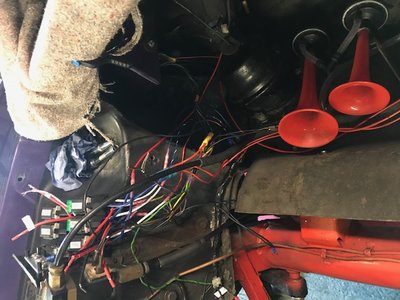
The loom has been opened right up from the branch that goes to the old horn relay to the nearside fog lamp. This allowed me to route the power lines to the relays without splicing more wire and having more points of failure. When it is finalised, I will rewrap the loom in non adhesive PVC loom tape and it will look original, apart from the modern relays. A price I'm willing to pay for safety and better electrical performance / reliability.
Come to think of it, I could fit a cover over the relays to hide them. Would be a good idea to help reduce corrosion, but I'm not sure what to make it from. Fibreglass I suppose, using an appropriately shaped and modified margarine container as a former.
Now some questions.. What is the anticipated amperage for each of the items being powered? I can calculate the lights (55W/12v=4.6A per lamp so 10A minimum for both, and the fogs are likely the same) but what about the air horn and radiator fan? I need to put a fuse in the feed wire next to the starter relay, and I need to use wire that is fat enough to carry the full load.
-

JonB - Coveted Fifth Gear

- Posts: 2358
- Joined: 14 Nov 2017
Ah-ha!
viewtopic.php?f=38&t=42470
..and..
viewtopic.php?f=38&t=37253
So, I'll use 4mm2 cable (42A) and see how it goes with a 35A fuse.
viewtopic.php?f=38&t=42470
..and..
viewtopic.php?f=38&t=37253
So, I'll use 4mm2 cable (42A) and see how it goes with a 35A fuse.
-

JonB - Coveted Fifth Gear

- Posts: 2358
- Joined: 14 Nov 2017
Yeah the labeller is a must, I think.
Kind of wished I'd bought a proper combined relay and fuse box now, these have the bus bars built in and look tidier, but probably would not fit at this location.
Just pulled the upright flange things out to be resprayed. Will try to do a better job this time! And pulled the loom back from the flanges on the bottom of the bay because I decided I want to repaint the matt black area as it looks a bit tatty. Satin black, really.. if I can find some paint.
-

JonB - Coveted Fifth Gear

- Posts: 2358
- Joined: 14 Nov 2017
JonB wrote:Kind of wished I'd bought a proper combined relay and fuse box now, these have the bus bars built in and look tidier, but probably would not fit at this location.
I did this and fitted it on the vertical infront of the radiator. I kind of regret going that way as it difficult to see/access if you have issues. I cheaped out on buying the expensive crimping tool, so of course I am now having issues with the wiring. It not much fun trying to diagnose electrical faults with limited access, light and 30C+ garage. I now know the fault but haven't pulled the box to fix. I looked at your set up and thought its nice as would have taken me 5 mins to diagnose and fix my problem.
Of course all my fault for not doing right first time. My plan is a full custom rewire at some point to support AC install.
'73 +2 130/5 RHD, now on the road and very slowly rolling though a "restoration"
- mbell
- Coveted Fifth Gear

- Posts: 2643
- Joined: 07 Jun 2013
Ratchet crimp? Pah. What I've done is use standard crimp connectors, pull off the plastic shroud, insert the wire, fold the crimpy bit down with pliers (one side at a time so they overlap). Then check the wire is held tightly and solder the joint. Finally, heat shrink tube over the end of the wire (where the shroud would be if I'd left it in situ and crimped).
So.. I scored some S/S hex head M5 fasteners and shakeproof washers, fitted screw terminals to the relay wires, laid a new "fat boy" ground and 12v line and wired the bus bars up.
The power and ground wires got special treatment as I am not sure the screw terminaIs I'm using are thick enough to carry all that current. What I did was fit one to the wire as normal, then lay a second and third behind it with the crimp bit widened to go over the first one. Then put a nut & bolt through the hole and bend the second and third crimp flaps over the first one, then apply solder and round off with heat shrink. You can see them in the picture, they are in the 4th from left (central) position.
I still need to find a shroud for the bus bars and attach the relays somehow (not really keen on drilling more holes in the body) but it seems to be shaping up OK, so far.
Incidentally, fan and horn relay wiring is different to the lights as they are triggered by a connection to ground. That's why one of the white wires is connected to the +ve bus. The relays' colour coding is Red (power in), Blue (power out), Black (coil ground), White (coil +ve or "trigger").
-

JonB - Coveted Fifth Gear

- Posts: 2358
- Joined: 14 Nov 2017
Well, the problem with crimp connectors is they are so prevalent. Cheap, easy to use. It's a trap!
I am removing ALL of them from my car (even the few I put in). I decided for the nose cone I would use waterproof multi way connectors. This might cause a problem with pulling the lighting wires through small holes intended for Lucar connectors, but I don't care. I need reliability.
I am removing ALL of them from my car (even the few I put in). I decided for the nose cone I would use waterproof multi way connectors. This might cause a problem with pulling the lighting wires through small holes intended for Lucar connectors, but I don't care. I need reliability.
-

JonB - Coveted Fifth Gear

- Posts: 2358
- Joined: 14 Nov 2017
MarkDa wrote:Yes - do get a decent ratchet crimp tool - they're not that expensive.
I plan to next time I tackle a significant wiring job. I manged to "fix" the issue. I was using 12v switched purple wire from original horn relay as 12v input on my relay. I am not longer getting 12v on that wire. For now I've used an alternative switch 12v line.
Ironically during the investigation I manage to pull a earth wire out of a crimp connector, that was made with racketing crimp tool. But was those nasty crimp connectors. (I also had to change the relay as while it was clicking and delivering 12v the air horns didn't want to work.)
JonB wrote:I still need to find a shroud for the bus bars and attach the relays somehow (not really keen on drilling more holes in the body) but it seems to be shaping up OK, so far.
Looking good. I probably just find a little sheet of aluminum and fasten the relays to that and possibly use the air defector plate screws to mount that. looks like you have some stand off screws so just need suitable sheet of something (Plastic?) to cover them.
'73 +2 130/5 RHD, now on the road and very slowly rolling though a "restoration"
- mbell
- Coveted Fifth Gear

- Posts: 2643
- Joined: 07 Jun 2013
Hmm, I am in a couple of minds here. I spent 9 years in the RAF and some years thereafter in an astronomy lab creating many electronic 'boxes', all of them built from a drawing, all of them built to 'Milspec' and to my knowledge non of the 'planes they stuffed the boxes in have fallen from the skies.
The non-military 'boxes' I built for the star-gazers are still going strong, many years after I built them and they have been subject to absolute abuse by uncaring individuals who just wanted to collect data from the ether and (almost) resented the fact that they had to use electronikery to do so - they just whacked these things into their conveyances and hied off to whichever observatory they were using for that project.
ALL of the connections I made on all of the above over these years were ALL soldered.
Now, I know that there are some out there who will delineate (thanks, Mr Google ) the nasty effects of flux and not just on the brain!, the effect of heat, vibration etc right after the soldered area, incorrect temperatures - the list is yawningly endless - but as I said above, none of the 'planes where my boxes were bunged in have fallen from the sky (haven't checked the news to day so I may edit this) and the galaxy is exactly where the astronomers, partly using my creations, say it is.
Crimping - especially using the tools and methods today is as close as you can get to perfection.
So, given the choice, with the tools and knowledge available and not just gained via the Internet, I would say - do whatever you feel most comfortable with.
As my pre-RAF journeyman electrician said to me - "you want a good electrical connection? You need a good mechanical connection"...but if you are good at the one versus the other...follow that route.
PS, I have also twisted bare wires together and temporarily insulated them with whatever was available, including Scotch Tape, to get any number of Lotus home...

 so don't necessarily follow my example.
PPS, great job there!
The non-military 'boxes' I built for the star-gazers are still going strong, many years after I built them and they have been subject to absolute abuse by uncaring individuals who just wanted to collect data from the ether and (almost) resented the fact that they had to use electronikery to do so - they just whacked these things into their conveyances and hied off to whichever observatory they were using for that project.
ALL of the connections I made on all of the above over these years were ALL soldered.
Now, I know that there are some out there who will delineate (thanks, Mr Google
Crimping - especially using the tools and methods today is as close as you can get to perfection.
So, given the choice, with the tools and knowledge available and not just gained via the Internet, I would say - do whatever you feel most comfortable with.
As my pre-RAF journeyman electrician said to me - "you want a good electrical connection? You need a good mechanical connection"...but if you are good at the one versus the other...follow that route.
PS, I have also twisted bare wires together and temporarily insulated them with whatever was available, including Scotch Tape, to get any number of Lotus home...
PPS, great job there!
- Slowtus
- Third Gear

- Posts: 371
- Joined: 22 Sep 2017
A reliable long term connection requires a gas-tight seal to avoid oxidation of the contacts, and in an automotive application mechanical strength also is important - no good if your fancy gas-tight connector falls apart with the vibration.
Soldering is a cheap and easy way to guarantee a good initial connection, and a long term seal. Crimping is fine in a production environment, with the cable size matched to the connector and proper tooling forming the crimp - but this hard to replicate DIY.
Personally, I crimp, then solder and use heat shrink to cover the connector.
FWIW, spade (lucar) connectors do form a gas tight seal (there is high contact pressure along the edges of the connector where it curls around the spade), bullet connectors do not, and are therefore guaranteed to fail.
68 Elan S3 HSCC Roadsports spec
71 Elan Sprint (still being restored)
32 Standard 12
Various modern stuff
71 Elan Sprint (still being restored)
32 Standard 12
Various modern stuff
- Andy8421
- Coveted Fifth Gear

- Posts: 1223
- Joined: 27 Mar 2011
40 posts
• Page 1 of 3 • 1, 2, 3
Total Online:
Users browsing this forum: No registered users and 34 guests

