Wiring an air horn - good electricians/advice appreciated
17 posts
• Page 1 of 2 • 1, 2
Hi I am taking my Sprint for its MOT and the horn sound is pitiful so a couple of questions
1) Am I missing something on the standard set up- I have renewed the horn pencil and contact ring as they were both worn and I have a solid UJ set up so the earth shouldn't have a problem there. I have run a separate earth from the rack to the chassis again no improvement. Any ideas I have checked old posts but cannot find an answer that helps me
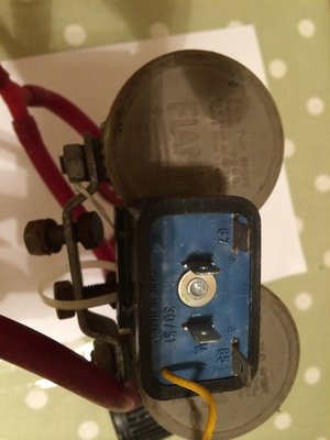
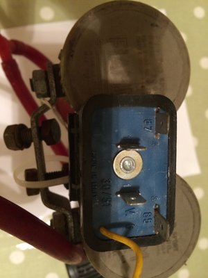
2) A friend has given me a twin set of 1970's Fiamm Series 2000 twin horns which came of a Ferrari I believe which have been tested by him and work. I wanted to put these in as they are slightly period but I am pretty useless in regards electricals. I have attached a picture of the relay and in the absence of any wiring diagrams could anybody provide advice as to what feed goes where. I have ascertained that terminal 87 leads to the positive terminal on the compressor 85 comes direct from the horn which is the pb lead and 30/51 is the live feed from the fusebox. I am going to put in an in-line fuse rated at 45 amps. Can anyone tell me why the yellow wire is and where does it go and the other terminal alongside the 30/51 does.
Mike
Mike
1971 Lotus Elan Sprint
1963 1071 Cooper S
1971 Lotus Elan Sprint
1963 1071 Cooper S
- Bahamayellow
- Second Gear

- Posts: 108
- Joined: 12 May 2009
Obviously no knowledgable electricians on the Forum 
Mike
1971 Lotus Elan Sprint
1963 1071 Cooper S
1971 Lotus Elan Sprint
1963 1071 Cooper S
- Bahamayellow
- Second Gear

- Posts: 108
- Joined: 12 May 2009
Lots a times, if it is topic that has been discussed numerous times, people get tired answering the same questions over and over. A quick search of horn wiring, showed 86+ topics devoted to the topic.
Were you able to do a quick search and not find what you needed?
jeff
Were you able to do a quick search and not find what you needed?
jeff
Jeff Cocking
LotusElan.net
LotusElan.net
-

jcocking - Second Gear

- Posts: 182
- Joined: 06 Sep 2003
Jeff in question 1) I put that I had searched through previous posts and covered all the possibilities.
I was really just after help on the relay but will check the posts again in regards relays and put on a Mini Cooper forum I'm on as they are pretty helpful.
I was really just after help on the relay but will check the posts again in regards relays and put on a Mini Cooper forum I'm on as they are pretty helpful.
Mike
1971 Lotus Elan Sprint
1963 1071 Cooper S
1971 Lotus Elan Sprint
1963 1071 Cooper S
- Bahamayellow
- Second Gear

- Posts: 108
- Joined: 12 May 2009
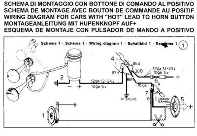
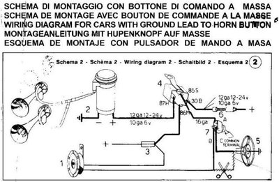
Mike - I don't know if this helps.
It's a wiring diagram for air horns - the relay numbers don't all match what you have quoted however.
It's a wiring diagram for air horns - the relay numbers don't all match what you have quoted however.
Steve
'64 S1 Elan (Owned since '73)
'69 Alfa Romeo 1750 Spider Veloce (Owned since '77)
'70 Morris Minor 1000 (Owned since '85)
'64 S1 Elan (Owned since '73)
'69 Alfa Romeo 1750 Spider Veloce (Owned since '77)
'70 Morris Minor 1000 (Owned since '85)
-

AlfaLofa - Third Gear

- Posts: 459
- Joined: 19 Aug 2006
1 have you tried connecting the horn directly to a 12v source to see that they work correctly? I believe some times the compressor need taking apart and lubricating.
I'd figure out if the problem is with the wiring or the actually horns. If it's wiring I'd just fix it and keep current horns. If it's horns/compressor I'd swap in the other ones but keep the lotus relay and wiring not the relay fastened to the horns.
I'd figure out if the problem is with the wiring or the actually horns. If it's wiring I'd just fix it and keep current horns. If it's horns/compressor I'd swap in the other ones but keep the lotus relay and wiring not the relay fastened to the horns.
'73 +2 130/5 RHD, now on the road and very slowly rolling though a "restoration"
- mbell
- Coveted Fifth Gear

- Posts: 2643
- Joined: 07 Jun 2013
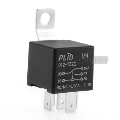
... and relays are relatively inexpensive. Might be easier than trying to determine what pins are what on the one you have. I'd get one that has the contact diagram printed on it. This is one from Fleabay but any 30/40A automotive relay will work.
The air horn compressor only needs a 12V hot lead and a ground to operate. The ground is hard wired to a known good ground point.
The relay needs a 12V input (85) to operate the field coil and a ground (86) for the field coil that is controlled by the horn push (switch). It also needs a 12V input (30) that is switched. The output (87) is switched into the horn compressor hot lead when the relay is activated.
Hope that helps.
Added... And all that assumes your Sprint is negative ground.
Bud
1970 +2S Fed 0053N
"Winnemucca - says it all really!!"
1970 +2S Fed 0053N
"Winnemucca - says it all really!!"
- Bud English
- Fourth Gear

- Posts: 942
- Joined: 05 Nov 2011
My compressor has a small oil 'nipple' for want of a better word.
The pump was unreliable at the best of times, unless regularly fed with a few drops of oil.
The pump was unreliable at the best of times, unless regularly fed with a few drops of oil.
- persiflage
- Second Gear

- Posts: 178
- Joined: 24 Jul 2005
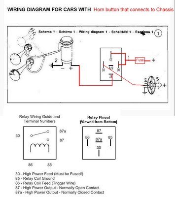
The wiring diagram above is for a car in which the horn putton is on the live side of the circuit which is not the case in our Lotuses; our horn push connects to the chassis.
I have drawn up a wiring diagram which will work. It is not the only possible way the wires can be connected on the relay pins, but this one will work. It uses the standard automotive pin numbers and the relay part of the diagram is upside down to make the layout of the drawing easier.:
Note that with all car wiring systems, your best friend is an electrical multimeter and the digital ones are so inexpensive nowadays that there is no real excuse for not having one.
You can't really diagnose electric problems unless you can "see" what the electricity is doing.
Second best friend is remembering what they taught you about electricity at school.
~~~~~~~~~~~~
Your relay pin numbers are not the same as standard automotive relays as shown in the photo above, so your first step should be to use a multimeter on ohms range to work out which are the connections to the relay coil and which are the contacts which close when the relay is activated.
Or pop along to a motor parts shop and buy a standard relay.
Last edited by billwill on Sat Jul 12, 2014 1:55 pm, edited 4 times in total.
Bill Williams
36/6725 S3 Coupe OGU108E Yellow over Black.
36/6725 S3 Coupe OGU108E Yellow over Black.
- billwill
- Coveted Fifth Gear

- Posts: 4417
- Joined: 19 Apr 2008
Thanks Guys this is really helpful as I can follow a wiring diagram but my electrical knowledge is poor. I think as suggested that I will try a standard relay. I have tried horns straight to live feed and they work. I think the yellow wire may be an earth
I don't really want to keep the original horns on the car as they do not alert other drivers; I had someone today nearly turn across in to me on a roundabout, it was only her passenger that alerted her that I was alongside.
Thanks for all the advice Mike
I don't really want to keep the original horns on the car as they do not alert other drivers; I had someone today nearly turn across in to me on a roundabout, it was only her passenger that alerted her that I was alongside.
Thanks for all the advice Mike
Mike
1971 Lotus Elan Sprint
1963 1071 Cooper S
1971 Lotus Elan Sprint
1963 1071 Cooper S
- Bahamayellow
- Second Gear

- Posts: 108
- Joined: 12 May 2009
Mike / Gents,
Excuse me for dropping in on this one, but I am just re wiring my horns and have a couple of additional queries on this subject:-
What was the original horn(s) spec for a Sprint ?
Mine was fitted with a Hi-Lo set and air horns, was this normal ?
If this was the case, (both sets being fitted) - how did they work - all on together when the Horn Push was pressed ?
As shown in the wiring diagrams above, when was/would the flick switch be used ?
I have added fused relay protection to both of the horn sets I have installed, but can't seem to get them to work together, although they both work when individually tested ?
Bill, I look forward to your thoughts ?
Regards,
Phil.T.
Philip.
UK '72 Sprint DHC
Sometimes my Lotus makes me cry.
UK '72 Sprint DHC
Sometimes my Lotus makes me cry.
-

l10tus - Third Gear

- Posts: 476
- Joined: 10 Apr 2008
l10tus wrote:Mike / Gents,
Excuse me for dropping in on this one, but I am just re wiring my horns and have a couple of additional queries on this subject:-
What was the original horn(s) spec for a Sprint ?
Mine was fitted with a Hi-Lo set and air horns, was this normal ?
Regards,
Phil.T.
I'm sure it was "either or" not both! My Sprint just has the high/Low electrical horn.
Phil Harrison
1972 Elan Sprint 0260K
1972 Elan Sprint 0260K
-

pharriso - Coveted Fifth Gear

- Posts: 3186
- Joined: 15 Sep 2010
17 posts
• Page 1 of 2 • 1, 2
Total Online:
Users browsing this forum: No registered users and 9 guests

