Wiper switch problem
13 posts
• Page 1 of 1
Help or suggestions please.
My wiper switch works fine on the bench, with a multimeter or connected to a battery and test light all works well.
In the car... only fast speed!
Connecting the wires with spade connectors in the car all works fine - slow speed and fast speed and parking. But with the switch... only fast and parking, no slow.
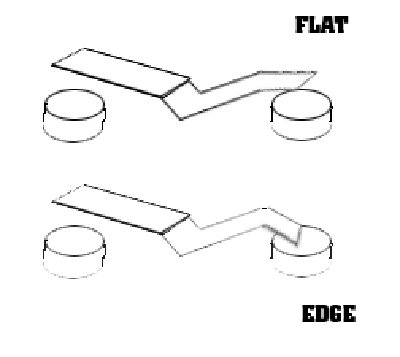
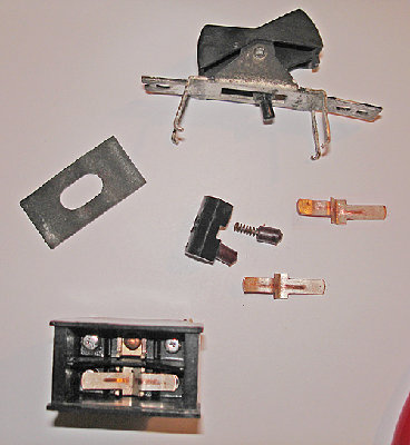
I've had the switch apart and together several times, can anyone tell me if the little 'V' shaped rocker should ideally connect flat with the terminal? coz mine is 'edge' touching. Would this affect the connection with a high load item like a wiper motor? - that will be my next test, when I get time.
-

SADLOTUS - Fourth Gear

- Posts: 517
- Joined: 19 Oct 2003
Hi Mathew, the wiring diagram has four wires going into the wiper switch and four plus earth into the wiper motor, with a green feed spur off one of the wires, so not much help there..
It's the correct switch - there's only one wired this way and checked against the Dave Bean catalogue.
Also checked the 'internal circuitry' of the switch but I will try and research to check. Logically it should work! But then who said anything about logic.
It's the correct switch - there's only one wired this way and checked against the Dave Bean catalogue.
Also checked the 'internal circuitry' of the switch but I will try and research to check. Logically it should work! But then who said anything about logic.
-

SADLOTUS - Fourth Gear

- Posts: 517
- Joined: 19 Oct 2003
Gene
No,slow is a seperate winding in the wiper motor (5-1) wheras fast is (3-1) where 1 is the earth connection...
John
No,slow is a seperate winding in the wiper motor (5-1) wheras fast is (3-1) where 1 is the earth connection...
John
-

john.p.clegg - Coveted Fifth Gear

- Posts: 4533
- Joined: 21 Sep 2003
The two speed wiper switch is a three circuit switch. The first circuit sends + current to the "fast" motor windings. The second circuit sends current to the "slow" motor windings. A + feed wire goes to the switch to accomplish this. It is, if memory serves, switched (ign.) and fused.
The park feature is also switched. It is the third switch function. This position grounds the internal park switch which is located in the wiper body. Contrary to the other circuits the park feature gets its + power at the wiper connector. The switch grounds it to complete the connection, which is broken as the wipers park.
The switch gets one ground( Black), one + feed (purple?), one "fast" and one "Slow" feeds, and one connection to the park function.
Hope this helps.
Bob
- rdssdi
- Fourth Gear

- Posts: 965
- Joined: 30 Sep 2003
I have recently moved to a new home an cannot locate my notes on the wiper circuit. I am working from a poor memory. Please accept this correction to my previous posting.
The park circuit is not a switch to ground rather, when "off" is selected at the dash wiper switch, the slow winding circuit is connected to the park "wire" that comes from the wiper motor. This park circuit is energized at the wiper motor. This "park" wire serves to energize the slow windings, stopping when the internal wiper park switch is open or off when the wipers are in the "park" position.
So, the four wires at the switch are: Power (+), slow windings, fast windings, wiper park circuit.
The colors MAY be - green (power), yellow, black/yellow, light green.
Again, sorry for the previous misinformation.
Bob
- rdssdi
- Fourth Gear

- Posts: 965
- Joined: 30 Sep 2003
Hi John, Bob, Gene, Mathew
Thanks for your posts, I read and printed them out and took them into the garage, crawled around the footwell and behind the dash for over an hour.
Having started this thread i thought i should contribute some more, and as you know, nothing is ever simple. The four wires arriving at the switch are: grn/blu, grn/brn, grn/red and grn/w. With ignition on, grn/w is live.
By connecting wires to each other in the car I (thought) could see which wire did what.
On the bench I can wire the switch so that: grn/w to grn/blu = slow wipers on first click of switch, and with the same wiring: grn/w to grn/brn = fast wipers on second click of switch.
When grn/red is connected the wipers will park.
(All done witha small 12 battery and bulbs)
BUT, when wired in the car, no slow... fast yes and park yes.
BLOODY!!
As I said earlier, I took the switch apart, I was very careful when I took it apart... obviously not careful enough! even though the circuitry looked like it should work on the bench, (the bench .. again!) in the car it wouldn?t.
SO, I thought, right, what have I to lose? (I still have a fuse between solenoid and battery lead) I put the switch back together purposely the wrong way round (not upside down, but with internals swapped left to right). AND HEY!! the bleedin? thing worked perfectly! Oddly, and I don't remember this from before, the wipers now park on the driver?s side...UH?!
In conclusion.
I ?tinned? the terminals inside the switch with a soldering iron to make better contacts and carefully bent the 'rockers' to make better contact.
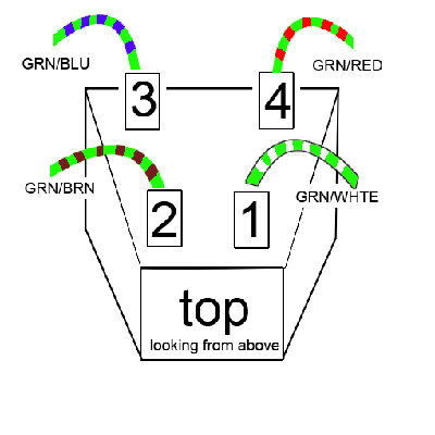
The (new?) wiring of the switch is:
(looking from above- see diagram)
top/off: contacts 3 & 4
middle/slow: contacts 2 & 4
bottom/fast:: contacts 2 & 1
top position/off: grn/blu and grn/red
middle position/slow: grn/brn and grn/red
bottom position/fast:: grn/brn and grn/w
self parks with these connections.
Sorry the above is a bit long winded, but I hope it might be useful to others. I also hope that it's correct!
Shows how that elusive electricity can be a real bugger to us mere mortals!
Anyway, thanks chaps, happy ME!
Last edited by SADLOTUS on Wed Nov 21, 2007 2:12 pm, edited 1 time in total.
-

SADLOTUS - Fourth Gear

- Posts: 517
- Joined: 19 Oct 2003
Well that helps,who said "a picture paints a thousand words" your switch is not the rotary type like mine,no wonder I've been scratching my head. But electrically I suppose it's the same....
John
John
-

john.p.clegg - Coveted Fifth Gear

- Posts: 4533
- Joined: 21 Sep 2003
Hi John, thanks for your help and actually what you said did help in identifying which wire did what and what to look for.
This morning, I fitted the switch with fingers crossed, everything worked - without the hesitant wiggle to the switch to make slow speed work as in the old days.
For other poor electically lacking brains out there like mine here's a bit more info: By disconnecting each wire individually:
grn/red=park
grn/blu=slow
grn/brn=fast
grn/whte=live
earth is from the wiper motor to bottom left dash bolt/earth point.
(ahem) sorry I doubted you Mathew.
-

SADLOTUS - Fourth Gear

- Posts: 517
- Joined: 19 Oct 2003
I found this thread really useful after discovering that only the fast speed worked reliably. Slow speed worked only intermittently if I wiggled the switch.
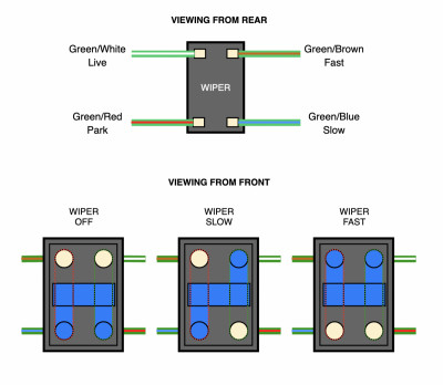
The problem I had was that the contacts were a bit misshapen and it took a little while to figure out the getting the switch to work especially as most diagrams show the rear of the switch and to reassemble you need to look at the front. A picture saves a thousand words so I hope this will help someone else.
The 3 states are shown in the diagram indicating which contacts need to be connected to get the switch to work. Just make sure that in the resting state (without the rocker connected) that the slow circuit has continuity. Mine didn't reliably make contact but after a slightly adjustment of the angle of the rocker contacts it all worked fine.
Hope that helps.
Andy
Elan Coupe 36/5245
Instagram: @sidney_the_elan
https://www.thingiverse.com/andy_makes_spares/designs
- lowflyer
- First Gear

- Posts: 25
- Joined: 17 Aug 2020
13 posts
• Page 1 of 1
Total Online:
Users browsing this forum: No registered users and 55 guests


