+2 chassis replacement questions
46 posts
• Page 3 of 4 • 1, 2, 3, 4
Sounds like a good plan, how long do you anticipate that taking.
Couple of other points, you?ve probably got them but not listed them. Give the trunnions a thorough check, and what fans are you going to use on the radiator.
Couple of other points, you?ve probably got them but not listed them. Give the trunnions a thorough check, and what fans are you going to use on the radiator.
Change is inevitable, except from a vending machine!
- Bigbaldybloke
- Fourth Gear

- Posts: 889
- Joined: 16 May 2017
Glad to hear that the chassis is all good Kevin. I just spotted this post and was a bit worried reading your first concerns, but relaxed now!
With the replacement chassis the mounting platform for the steering rack will need to be measured up to calculate the shims required to overcome bump-steer. Easy enough to do with the body off.
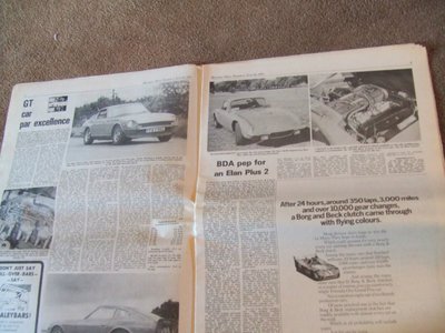
And look what I found on ebay last week. I had been looking for this copy of Motoring News for years now as it has the article about your car. I saw the front cover, thought I recognised the date but though it very unlikely that it would be the one...but it is, and it's in very good condition.! I'll bring it up to you when you do the first hill climb.
Mark
-

Elanintheforest - Coveted Fifth Gear

- Posts: 2496
- Joined: 04 Oct 2005
Yes please Mark.
Re the rack shims, I thought Lotus stamped a number on the rack position with the thickness reqd ??
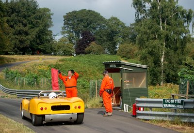
As you could see, I am planning a very complete rebuild, and hope to be at Loton Park at the end of March for their first event, fingers crossed.
Kevin
Re the rack shims, I thought Lotus stamped a number on the rack position with the thickness reqd ??
As you could see, I am planning a very complete rebuild, and hope to be at Loton Park at the end of March for their first event, fingers crossed.
Kevin
- kwhittle
- Second Gear

- Posts: 67
- Joined: 19 Jun 2016
I think that the shim sizes were scratched on which may make them hard to find if they are still visible!
That little lot shouldn't be a huge job with the body off the chassis. Looking through the old notes, the gearbox and differential were overhauled in the restoration, but that was 20 odd years ago now even if no miles, so things like the oil seals at least will need replacing. I have a new-old-stock 3.54 differential bought for my S3 Elan 30 years back that I was going to pop in, but have been told that the bearings and seals will need replacing as nothing has moved in 40 years. We live and learn!
That little lot shouldn't be a huge job with the body off the chassis. Looking through the old notes, the gearbox and differential were overhauled in the restoration, but that was 20 odd years ago now even if no miles, so things like the oil seals at least will need replacing. I have a new-old-stock 3.54 differential bought for my S3 Elan 30 years back that I was going to pop in, but have been told that the bearings and seals will need replacing as nothing has moved in 40 years. We live and learn!
-

Elanintheforest - Coveted Fifth Gear

- Posts: 2496
- Joined: 04 Oct 2005
Nice easy job to do the Shimming with a bare Chassis
Alan
Alan
Alan.b Brittany 1972 elan sprint fhc Lagoon Blue 0460E
- alan.barker
- Coveted Fifth Gear

- Posts: 3757
- Joined: 06 Dec 2008
I have numbers on the frame
LH 30, and rh 40.
I assume thou.
Failing that I would have assembled the F suspension minus the shocks and lifted the F uprights with the steering centralised, so as to minimise the toe in/camber changes.
I assume that's to Buckland method ?
Kevin
LH 30, and rh 40.
I assume thou.
Failing that I would have assembled the F suspension minus the shocks and lifted the F uprights with the steering centralised, so as to minimise the toe in/camber changes.
I assume that's to Buckland method ?
Kevin
- kwhittle
- Second Gear

- Posts: 67
- Joined: 19 Jun 2016
The Brian Buckland method is to put a straight edge on top of the top wishbone spindles and measure down to the steering rack pads. The dimension should be 158mm. Shim to achieve this dimension. To be honest yours sound about right.
Dave
Dave
Elan +2
Elise mk 1
Elise mk 1
- Donels
- Fourth Gear

- Posts: 710
- Joined: 10 Sep 2016
Has anyone done any calculations or accurate measurements to indicate how sensitive the suspension is to rack height. I?m thinking if the rack is say 1mm ( 40 thou ) low what does that equate to in bump steer at full rise and fall of the suspension assuming the toe in is correct at normal ride height. Figure could be either in degrees of movement or distance measured between rims. My guess is that for anything less than about 1mm error in rack height the amount of bump steer will be almost too small to measure unless you are on a laser alignment jig.
Change is inevitable, except from a vending machine!
- Bigbaldybloke
- Fourth Gear

- Posts: 889
- Joined: 16 May 2017
Donels wrote:The Brian Buckland method is to put a straight edge on top of the top wishbone spindles and measure down to the steering rack pads. The dimension should be 158mm. Shim to achieve this dimension. To be honest yours sound about right.
Dave
Hi Dave
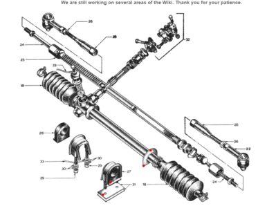
I'm very interested in measuring my +2 which I assume is the same steering setup. Is there a diagram showing exactly where to measure from / to? What are the rack "pads"?
-

JonB - Coveted Fifth Gear

- Posts: 2359
- Joined: 14 Nov 2017
Put a straight edge on top of the top wishbone spindles and measure down to the steering rack pads. These are the sticking out bits at the front of the chassis that the steering rack sits on. Shim accordingly. The dimension should be 158mm and applies to the baby Elan and +2, according to Brian.
Elan +2
Elise mk 1
Elise mk 1
- Donels
- Fourth Gear

- Posts: 710
- Joined: 10 Sep 2016
My understanding of bump steer is that with the unequal length top and bottom wishbones of the Elan it is not possible to get zero bump steer through the full range of suspension travel. This is because with the shorter top wishbone the camber changes as the wheel goes up and down, which means that the top of the upright gets nearer the centre of the car at full suspension travel. Assuming nothing else changes, the track rod would have to get shorter to compensate for this otherwise you would get some bump steer. For zero bump steer the track rod need s to stay parallel to the wishbones and the inner end of the track rod should be in line with the inner ends of the wishbones and then the outer ends will all go up and down in a similar arc and hence will not cause the upright to turn. This all depends on lots of tolerances, the main ones being the length of the track rod ball joint and how far the upright is screwed into the trunnion. So I?m assuming the method described aims to minimise this by setting up the rack in the straight ahead position at normal ride height, which is probably a good starting point if all the other dimensions are as designed, any changes due to after market tolerances on trunnions, uprights and ball joints may well affect this, so if you have the body off the only way to be 100% sure is to measure the toe in over the full range of suspension travel. For road use the measurement from spindles to rack support is probably sufficient but it would be interesting to hear what the people with race cars do to set up their suspension.
Just as an aside, I race radio control cars that have fully adjustable suspension and one of the most critical settings is the number of shims in the joint between the track rod and the steering arm on the hub, this makes a big difference to the amount of bump steer.
Just as an aside, I race radio control cars that have fully adjustable suspension and one of the most critical settings is the number of shims in the joint between the track rod and the steering arm on the hub, this makes a big difference to the amount of bump steer.
Change is inevitable, except from a vending machine!
- Bigbaldybloke
- Fourth Gear

- Posts: 889
- Joined: 16 May 2017
The dimension is to the top surface of the sticking out bits on the chassis that the rack sits on. Shims are then placed on this surface to achieve the dimension quoted. Your closest red dot is the one on the shim in your picture.
Elan +2
Elise mk 1
Elise mk 1
- Donels
- Fourth Gear

- Posts: 710
- Joined: 10 Sep 2016
46 posts
• Page 3 of 4 • 1, 2, 3, 4
Total Online:
Users browsing this forum: No registered users and 13 guests


