ME NODIZ Pro GEN-X install in a Plus 2
27 posts
• Page 1 of 2 • 1, 2
Starting a thread to describe my installation of the NODIZ Pro GEN-X ignition only ECU. This cool little box provides 3D ignition capability to vintage carburetor engines. In addition it can sense and control coolant fans and data log wideband O2 AFR data with a modern tach output.
I am presently drawing together some information to post my progress so far.
Here are a few valuable links to this topic in no particular order….
This one is about the coil pack location
viewtopic.php?f=31&t=47916
Came up in a Nodiz search
viewtopic.php?f=39&t=51893
This one is about removing the stock crankshaft pulley from my car
This one is about installing the QED 36-1 trigger wheel pulley in my car
viewtopic.php?f=39&t=53547
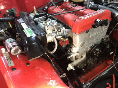
Here is a picture of my progress so far…
- Attachments
-
- February 2024 progress shot on my Nodiz Pro Gen-X installation. The QED 36-1 pulley and CPS mount are shown. Pulley first needed to be permanently marked for TDC. With the sensor mounted the required 90 degree advance for the missing tooth has to be marked out and the tooth removed with a grinder. Folks smarter than me would have probably remounted their fan belt first. All kidding aside, my fan belt has never been ideal, so I hopefully have the correct one on order. Mounting the fan belt is going to be more challenging because of the reduced clearance to the brake lines on my Spyder space frame. One can also see the current MSD dizzy that will be removed but retained for backup. Based on Damian’s experience I am really drawn to mounting the Gen-X in the cabin. I already have a perfect location in my Federal Plus 2 because the MSD system includes a larger 6AL module that will not be required. In addition I have an existing multi-connector on the right hand side interior with all of the required wires, including a AES wide band O2 signal which I would dearly love to add in to the mix so I can data log the AFR to finalize my jet selection.
Stu
1969 Plus 2 Federal LHD
1969 Plus 2 Federal LHD
-

stugilmour - Coveted Fifth Gear

- Posts: 2111
- Joined: 03 Sep 2007
In the photo above you can also see the Throttle Position Sensor. The custom bracket easily attached to my modern Weber 45’s with the provided M6 screws. M5 Screws are also provided to attach the provided sensor. In my case the sensor fit easily when clocked to the second set of mounting holes.
https://www.webcon.co.uk/products/9948- ... 4045-dcoe/
I also purchased the matching 3-pin mini timer rubber shielded connector from Webcon as I was not sure if the connector that ME uses for their TPS sensor loom option was the same, and more importantly they use the same pin configuration.
https://www.webcon.co.uk/products/16793 ... ector-kit/
Here for reference is a repost describing some of the other stuff I have to hand for this project …
I got the sensor mount and pulley from QED. They are in the links below:
https://qedmotorsport.co.uk/product/cra ... -36-teeth/
https://qedmotorsport.co.uk/product/cra ... g-bracket/
They also list the compatible Ford sensor, although I got mine from the ECU supplier instead.
https://qedmotorsport.co.uk/product/cra ... ford-type/
I am going with the ignition only version of Motorsports-Electronics ECU called the Nodiz Gen-X.
https://motorsport-electronics.co.uk/pr ... c-harness/
The Nodiz Gen-X seems to be a relatively new model. I believe the programming software is now similar to their fuel injection products, rather than earlier versions with mode buttons and some flashing LED’s. The box is water resistant and rugged looking, although still debating whether to mount it under the bonnet or in the interior.
The system will also use a throttle position sensor. I am using this one, which was a very complete & simple screw on kit. You do need to add the matching connector & boot to make up a short loom run to the main Nodiz connector, or specify this loom leg when you purchase the complete deal from ME.
https://www.webcon.co.uk/products/9948- ... 4045-dcoe/
For simplicity of installation I have opted to not use the other features included in the ignition only ECU, including coolant temperature and cooling fan control. I am happy with my already installed Clivey Boy fan controller.
Next on the list is to finish off the loom and unit mounting. I plan to test fire the engine before removing the dizzy. Once I am confident it functions OK I plan to permanently mount the Ford coil pack over top of the dizzy blanking plug; I got one one on eBay that looks a bit better than the QED offering. I am also using a coil pack mounting bracket from TriggerWheels.com, but that still needs some MacGyvering. The idea is the engine can easily be pulled by simply disconnecting the coil pack, TPS, and CPS at their respective sealed connectors and leaving the coil pack and wires in place.
Basically the plan is to retain my new style Weber 45’s but get better ignition performance. I am particularly wanting more advance at highway cruising speed with very small throttle openings. Struggling to get smooth engine performance and reasonable fuel economy without vacuum advance.
Once I get the Nodiz working I am hoping to do up a more complete thread on how it works and so forth. Although the ECU is preloaded with a suitable ignition curve the system will require one time only programming to set the position of the missing tooth relative to TDC. Other than the three connections to the engine, the only other wiring required is a four way connector with ground, pure clean 12v power supply, ignition trigger wire, and tach signal output, so the whole thing is really quite simple and slimmed down.
Anyway, I got the trigger wheel mounted and a very nice consistent gap to the sensor, although I had to bend the mount slightly. The QED mount included three 1 1/4” hex head cap screws, but I separately purchased longer socket head screws to stay consistent with the other oil pan fasteners. Hopefully I haven’t created a pan leak.
I am presently waiting on a correct fan belt, which has to be installed before the sensor is buttoned up for the final time.
https://www.webcon.co.uk/products/9948- ... 4045-dcoe/
I also purchased the matching 3-pin mini timer rubber shielded connector from Webcon as I was not sure if the connector that ME uses for their TPS sensor loom option was the same, and more importantly they use the same pin configuration.
https://www.webcon.co.uk/products/16793 ... ector-kit/
Here for reference is a repost describing some of the other stuff I have to hand for this project …
I got the sensor mount and pulley from QED. They are in the links below:
https://qedmotorsport.co.uk/product/cra ... -36-teeth/
https://qedmotorsport.co.uk/product/cra ... g-bracket/
They also list the compatible Ford sensor, although I got mine from the ECU supplier instead.
https://qedmotorsport.co.uk/product/cra ... ford-type/
I am going with the ignition only version of Motorsports-Electronics ECU called the Nodiz Gen-X.
https://motorsport-electronics.co.uk/pr ... c-harness/
The Nodiz Gen-X seems to be a relatively new model. I believe the programming software is now similar to their fuel injection products, rather than earlier versions with mode buttons and some flashing LED’s. The box is water resistant and rugged looking, although still debating whether to mount it under the bonnet or in the interior.
The system will also use a throttle position sensor. I am using this one, which was a very complete & simple screw on kit. You do need to add the matching connector & boot to make up a short loom run to the main Nodiz connector, or specify this loom leg when you purchase the complete deal from ME.
https://www.webcon.co.uk/products/9948- ... 4045-dcoe/
For simplicity of installation I have opted to not use the other features included in the ignition only ECU, including coolant temperature and cooling fan control. I am happy with my already installed Clivey Boy fan controller.
Next on the list is to finish off the loom and unit mounting. I plan to test fire the engine before removing the dizzy. Once I am confident it functions OK I plan to permanently mount the Ford coil pack over top of the dizzy blanking plug; I got one one on eBay that looks a bit better than the QED offering. I am also using a coil pack mounting bracket from TriggerWheels.com, but that still needs some MacGyvering. The idea is the engine can easily be pulled by simply disconnecting the coil pack, TPS, and CPS at their respective sealed connectors and leaving the coil pack and wires in place.
Basically the plan is to retain my new style Weber 45’s but get better ignition performance. I am particularly wanting more advance at highway cruising speed with very small throttle openings. Struggling to get smooth engine performance and reasonable fuel economy without vacuum advance.
Once I get the Nodiz working I am hoping to do up a more complete thread on how it works and so forth. Although the ECU is preloaded with a suitable ignition curve the system will require one time only programming to set the position of the missing tooth relative to TDC. Other than the three connections to the engine, the only other wiring required is a four way connector with ground, pure clean 12v power supply, ignition trigger wire, and tach signal output, so the whole thing is really quite simple and slimmed down.
Anyway, I got the trigger wheel mounted and a very nice consistent gap to the sensor, although I had to bend the mount slightly. The QED mount included three 1 1/4” hex head cap screws, but I separately purchased longer socket head screws to stay consistent with the other oil pan fasteners. Hopefully I haven’t created a pan leak.
I am presently waiting on a correct fan belt, which has to be installed before the sensor is buttoned up for the final time.
Stu
1969 Plus 2 Federal LHD
1969 Plus 2 Federal LHD
-

stugilmour - Coveted Fifth Gear

- Posts: 2111
- Joined: 03 Sep 2007
Appreciate the wright-up, as always Stu!
Born, and brought home from the hospital (no seat belt (wtf)) in a baby!
Find out where the limits are, and start from there
Love your Mother
Earth
Find out where the limits are, and start from there
Love your Mother
Earth
-

h20hamelan - Coveted Fifth Gear

- Posts: 2105
- Joined: 25 Sep 2010
I am fitting a DTAFast no distributor system to my Elan. I got it from QED, no instructions at all and the base map had incorrect info…
It looks like you used the same pully/sensor setup. Any pictures of which tooth you removed? I came to the conclusion I did need to remove one- but no response from QED yet.
I did read DTA instructions on setting angle of missing tooth vrs TDC, so I should be able to figure it out.
But very interested in what you do on yours.
Mark
1966 Lotus Elan S3- Benelli motorcycles (various)
- Lotus54
- Second Gear

- Posts: 132
- Joined: 10 Oct 2023
It may be different for the DTA setup, but for the Emerald one with a 36-1 trigger wheel they recommend the trailing edge of the missing tooth is at approx 90 BTDC. The QED bracket puts the sensor at approx 90 degrees BTDC, suggesting the missing tooth is aligned with the crank TDC on the number 1 cylinder. (This is what I did, but haven't got it fully built yet so can't confirm.)
The exact offset can apparently be adjusted in the software, but they recommend it is between 60 and 120 Deg BTDC.
The exact offset can apparently be adjusted in the software, but they recommend it is between 60 and 120 Deg BTDC.
- ill_will
- Third Gear

- Posts: 257
- Joined: 18 Apr 2008
Well described above. Hopefully I did it correctly, or of course the new pulley is toast. Really won't know if it works until we try to fire it up.
Here is my reasoning and procedure. Note the QED pulley is not marked for TDC when you receive it, so it is kind of a two step process.
As mentioned above they point out in the NoDiz instructions that the missing tooth has to pass the sensor head approximately 90 degrees ahead of TDC on cylinder one. This actually seems to be pretty standard across manufacturers. The idea is the missing tooth triggers the advance calculation well ahead of when spark is required. This gives time for the ECU to compute, and also makes the required advance to be available. Not sure where I read it, but one guy pointed out that really the ECU is calculating the amount to retard the spark from the initial triggering event at 90 degrees BTDC.
From that understanding, I figured the missing tooth has to be about 9 teeth ahead of the sensor location when the engine is at TDC.
I basically removed the original pulley, and used it to make a similar timing mark on the new QED pulley by carefully aligning the keyways. Then I used the new timing mark to get to TDC and marked the sensor location on the trigger wheel. The required missing tooth is nine teeth clockwise from where the sensor is at TDC.
I can't recall how I managed, but I only ended up having to mount the new pulley with the key once.
Hope that helps. It is kind of a confusing thing to describe, but when you are all done and have the engine at TDC on number one, the missing tooth will be 90 degrees after the sensor location.
I will add some better pictures when I get back into town.
I also considered the DTAFast setup and made an email request for a quote from QED, but they never got back. I decided to just get the bracket and trigger wheel from them.
I would have been keen on their package if I could get everything from one supplier, as shipping to Canada from multiple suppliers is more hassle and cost. When I did place the QED order for the wheel and bracket, they replied with a proper itemized quote (with all shipping and handling) and only then asked for payment.
So in the end it was probably my misunderstanding of their ordering procedure. I probably should have just made an online order for the stuff I figured I needed, and sort out any questions after they got back with an itemized quote. Oh well.
Stu
1969 Plus 2 Federal LHD
1969 Plus 2 Federal LHD
-

stugilmour - Coveted Fifth Gear

- Posts: 2111
- Joined: 03 Sep 2007
Unless I hear differently from QED soon, I will measure and remove a tooth on the setup I got from them. The DTAFast system goes into setting the degrees - I will go in the middle of the range and remove one.
QED sent no instructions (just the stuff from DTAFast, which are good, but generic). I asked for some, but they didn’t respond.
I will make a post describing what I did (after I make it work) to help anyone else doing it. Yes, too much money for return I’m sure, but for me- I think it will be worth it.
1966 Lotus Elan S3- Benelli motorcycles (various)
- Lotus54
- Second Gear

- Posts: 132
- Joined: 10 Oct 2023
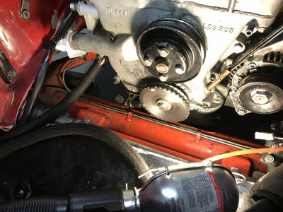
In case it helps. Here is a photo of my setup. QED pulley & CPS for Nodiz
The red line marks my crank's TDC and you can see where I have removed one tooth from the pulley.
So the missing QED tooth passes the Crank Position Sensor when the red line is approximately 90 degrees before the TDC mark on the front of the engine/water pump casting.
[NOTE: Photo was taken before I had properly adjusted the gap between CPS and pulley. It needs to be much closer than shown in photo]
Damian
67 French-Blue Elan S3 DHC 45/7001
67 French-Blue Elan S3 DHC 45/7001
- DamianB
- First Gear

- Posts: 44
- Joined: 04 Sep 2022
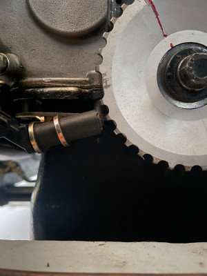
Looks like I did it correctly. This is the best picture I have on my phone. It shows the engine at TDC with the missing tooth approximately 90 degrees clockwise after the sensor.
- Attachments
Stu
1969 Plus 2 Federal LHD
1969 Plus 2 Federal LHD
-

stugilmour - Coveted Fifth Gear

- Posts: 2111
- Joined: 03 Sep 2007
Please let me know what you have (then finalize) on ignition map.
Mine has a preloaded one, but I am suspect on numbers.
I will save what is in there, then start with about what original distributor has- then modify for light throttle etc.
At least that is my plan now.
Mine has a preloaded one, but I am suspect on numbers.
I will save what is in there, then start with about what original distributor has- then modify for light throttle etc.
At least that is my plan now.
1966 Lotus Elan S3- Benelli motorcycles (various)
- Lotus54
- Second Gear

- Posts: 132
- Joined: 10 Oct 2023
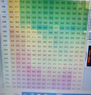
This is the advance map that came with the unit.
Those idle specs seem way, way too much- especially at no throttle. But perhaps that actually works?
Throttle opening across top (sorry- I cut it off).
RPM along left.
I did save original, but already changed those numbers so that idle is 10º and moving up more like what the specs in the Miles Wilkins book says. Certainly I will adjust later for best running and maybe better economy at very light throttle. Have to match up with carb settings of course. I have a wideband O2 sensor so can monitor while driving.
I would like to see what the NODIZ base settings are- it would be interesting.
BTW, it came with a quite high max RPM, I have changed it to do about 6700 max, with the gradual cylinder cuts before that. Maybe this is for a quite high spec engine? I do not know, I cannot get any info from QED.
1966 Lotus Elan S3- Benelli motorcycles (various)
- Lotus54
- Second Gear

- Posts: 132
- Joined: 10 Oct 2023
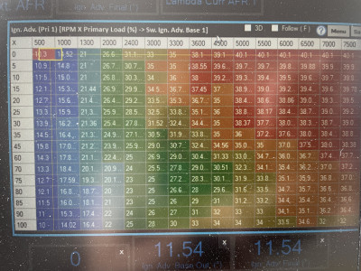
DamianB wrote:I have pasted here the ignition map from my Nodiz. Installed on a twincam, 420 cams with 40DCOEs.
In my case RPM across the top X Axis and Throttle % down the Y Axis
Thanks for posting Damian. Is that the ignition map that came pre-loaded on your NoDiz when shipped? Hoping I won’t have to alter the pre-flashed data other than the timing offset to correct for the exact missing tooth location.
Thx
Stu
Stu
1969 Plus 2 Federal LHD
1969 Plus 2 Federal LHD
-

stugilmour - Coveted Fifth Gear

- Posts: 2111
- Joined: 03 Sep 2007
27 posts
• Page 1 of 2 • 1, 2
Total Online:
Users browsing this forum: No registered users and 7 guests


