Battery cut off switch
74 posts
• Page 5 of 5 • 1, 2, 3, 4, 5
Hi,
I have used the method bob mentions, I posted a couple of pictures in Pistachio's original thread in the mods section on page 4 of that thread.
One of the benefits of this way is that, apart from a small switch tucked away under dash, the rest is hidden under the boot boards next to the battery.
Chris.
Last edited by tcsoar on Tue Feb 26, 2013 7:35 am, edited 1 time in total.
-

tcsoar - Third Gear

- Posts: 360
- Joined: 01 May 2007
Salut Chris
Just checked the RS link - you're using a special battery disconnect switch - a sort of bi-stable relay - I couldn't see how a momentary contact of your spring-loaded switch could permanently energise the coils.
Interesting but a bit pricey at ?70 + VAT.
@+
Vernon
Just checked the RS link - you're using a special battery disconnect switch - a sort of bi-stable relay - I couldn't see how a momentary contact of your spring-loaded switch could permanently energise the coils.
Interesting but a bit pricey at ?70 + VAT.
@+
Vernon
-

vernon.taylor - Fourth Gear

- Posts: 829
- Joined: 05 Nov 2010
Chris
I've just joined this debate...if you isolate the battery,be it ground/earth/negative or hot/live/positive via a relay via a switch,how can you reactivate it?
"The supply for the switch is taken from one of the permently live feeds behind the dash,"
John
I've just joined this debate...if you isolate the battery,be it ground/earth/negative or hot/live/positive via a relay via a switch,how can you reactivate it?
"The supply for the switch is taken from one of the permently live feeds behind the dash,"
John
-

john.p.clegg - Coveted Fifth Gear

- Posts: 5745
- Joined: 21 Sep 2003
Hi John,
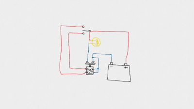
The relay is a latching type and has two coils, one to close the contact and one to open. If the relay is open and you energise the close coil, it will close the contact and it stays closed when the close coil is de-energised. Once the relay is switched the coils do not need to be energised to keep it in either position. The opposite happens when you then energise the open coil.
When I installed the relay I connected the negative side of the coils to the battery side of the relay. Therefore when the relay is open I flick the switch to put the positive feed onto the close coil, the negative side of the coils is already conected to the battery so it operates and closes the relay, I then release the switch. Again, opposite to open the realy.
Someone mentioned that by connecting it to a live feed there is a risk of cables shorting against the chassis/earth, this could be said of any live cable with in the car. The reason that I fitted this was to make the car electrically safe when parked up overnight, disconnecting the earth to the battery does this.
For more info type 'Tyco battery disconnect switch' into Google, this will lead you to a pdf page with all the spec.
Chris.
-

tcsoar - Third Gear

- Posts: 360
- Joined: 01 May 2007
Chris
I have no problem understanding the operation of bi-stable relays, but the statement......
"The supply for the switch is taken from one of the permanently live feeds behind the dash,"??
How do you have a live feed behind the dash with the battery disconnected??
John
I have no problem understanding the operation of bi-stable relays, but the statement......
"The supply for the switch is taken from one of the permanently live feeds behind the dash,"??
How do you have a live feed behind the dash with the battery disconnected??
John
-

john.p.clegg - Coveted Fifth Gear

- Posts: 5745
- Joined: 21 Sep 2003
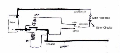
After a little puzzlement I see that the essence of Chris' circuit and the reason the the relay coils can function is that it isolates all the circuits EXCEPT the return path for the solenoid coils; they are connected to the non-isolated side of the main contacts, i.e. directly to the negative terminal of the battery. However since they are only momentarily operated, this is a very low risk.
Chris left off the essential element of the chassis itself from his quick sketch of the circuit. If I may be permitted: I would probably draw the circuit like this:
Chris left off the essential element of the chassis itself from his quick sketch of the circuit. If I may be permitted: I would probably draw the circuit like this:
Bill Williams
36/6725 S3 Coupe OGU108E Yellow over Black.
36/6725 S3 Coupe OGU108E Yellow over Black.
- billwill
- Coveted Fifth Gear

- Posts: 5062
- Joined: 19 Apr 2008
Thanks for the diagram Bill, the program I used for mine would not let me put in any text so I went for the 'make it simple' approach. The light bulb was a last minute addition to try and indicate the cars other loads.
Mark, I have installed an in line fuse in the feed to the switch but didn't show it in the sketch.
Chris
Mark, I have installed an in line fuse in the feed to the switch but didn't show it in the sketch.
Chris
-

tcsoar - Third Gear

- Posts: 360
- Joined: 01 May 2007
I've fitted an isolator to my Type 26 exploiting the closeness of the battery to the chassis bolt it usually connects to. I used a scrap piece of Ali T-bar and sculpted it to avoid the bobbin etc and sleeved the battery lead and enclosed the isolator underside in an old can lid. I'm disappointed that the resistance seems to be 0.004 Ohms which doesn't seem much until you pass 150 Amps through it, dropping 0.6 Votls.
I'm having trouble posting at the moment so details and photos may not appear!
I'm having trouble posting at the moment so details and photos may not appear!
Meg
26/4088 1965 S1½ Old and scruffy but in perfect working order; the car too.
________________Put your money where your mouse is, click on "Support LotusElan.net" below.
26/4088 1965 S1½ Old and scruffy but in perfect working order; the car too.
________________Put your money where your mouse is, click on "Support LotusElan.net" below.
-

Quart Meg Miles - Coveted Fifth Gear

- Posts: 1278
- Joined: 03 Oct 2012
Underside of assembly without shield fitted (to wooden block).
Meg
26/4088 1965 S1½ Old and scruffy but in perfect working order; the car too.
________________Put your money where your mouse is, click on "Support LotusElan.net" below.
26/4088 1965 S1½ Old and scruffy but in perfect working order; the car too.
________________Put your money where your mouse is, click on "Support LotusElan.net" below.
-

Quart Meg Miles - Coveted Fifth Gear

- Posts: 1278
- Joined: 03 Oct 2012
74 posts
• Page 5 of 5 • 1, 2, 3, 4, 5
Total Online:
Users browsing this forum: No registered users and 13 guests


