Bill's 26S
Bill,
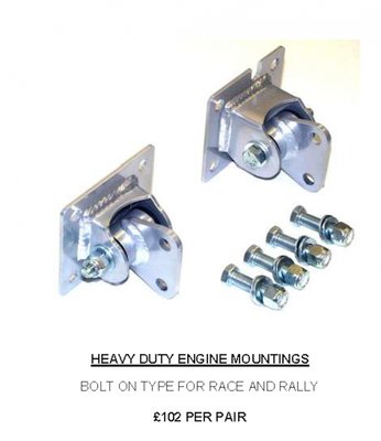
There is another engine mount supplier I just remembered, Milton Race, who specialize in Anglia 105E competition parts.
http://www.miltonrace.co.uk
There is another engine mount supplier I just remembered, Milton Race, who specialize in Anglia 105E competition parts.
http://www.miltonrace.co.uk
Russ Newton
Elan +2S (1971)
Elite S2 (1962)
Elan +2S (1971)
Elite S2 (1962)
-

CBUEB1771 - Coveted Fifth Gear

- Posts: 1546
- Joined: 09 Nov 2006
Hi Russ, thanks for the additional motor mount info.
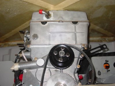
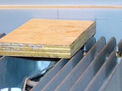
I resolved the bonnet height to cam cover clearance issue since my last post. The engine needs to be lowered about 5/16 inch to allow 1/8 inch clearance with the underside of the bonnet. The start position was based upon the OEM style HD mount (Stromberg style-lower on carb side than the Weber setup).
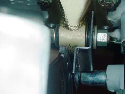
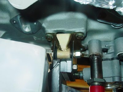
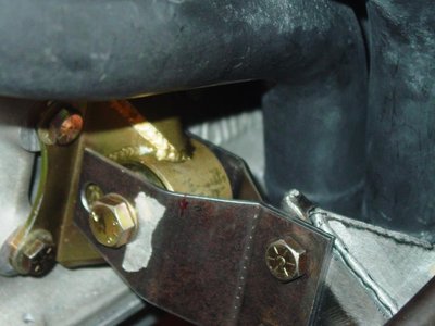
I managed to get my hands on a set of Kelvedon street (big bushing) motor mounts from Russ, thank you Russ, and tried to install them on the exhaust side of the engine, but with links to accommodate a bushing height, 1/4 inch lower than OEM Stromberg HD mounts, to rectify bonnet clearance issues. The bushing carrier easily bolted to the block. The chassis is flexible enough in the motor mount plane that it is possible to force fit the Kelsport mounts by spreading the pre stressing the chassis about 1/4 inch, not a good thing. This motor mount kit does not work for me as is. It didn?t fit on my chassis/engine combination where OEM spec mounts fit fine. Dimensions are different. The Kelvedon stack of 2 pieces was longer than the TTR HD mounts they replaced. The best solution for me was to fabricate replacement chassis to bushing links that could work in the confined space. Further, the carb side Kelsport links had two right angle bends each and the rear one needed to pass between the carb side chassis motor mount bracket and the Kelsport motor mounted bushing carrier.
This design would not work for the back side link as there was a maximum of only 0.050 inches clearance between the chassis motor mount bracket and the engine mounted bushing carrier. The other issue was the engine still needed to go down, about 1/4 inch at this location.
So, I decided to change the design of the carb side links and replace them with non-bent parallel links, anchored by large, stiff standoffs. I need to get the geometry right and my first attempt with this design works pretty good, but a bit heavy. The back side spacer/standoff can be slimmed down about 1/8 inch to thickness of 3/8 inch. I plan to make the final link pieces out of 416 (marine grade) stainless. This mount is much stiffer without the bends, so 0.075 thick should be fine. The Kelsport bent links appear to be 2 mm (0.080 inches) mild steel with a passivation coating.
The interesting question is whether it makes sense to lower the engine even more for a lower CG and what effect this will have on the exhaust system height and rocking clearance between the tranny and the chassis bulkhead, near the speedometer sender.
The good news now is that the body is at the original fitted height, the bonnet clears the cam cover, and the bonnet perimeter fits the surrounding bodywork with the air box in its installed position. I may wait, until I next take the body off, to fabricate the final motor mount pieces. There may yet be some clearance issues that need to be discovered and refined.
Bill
- bill308
- Fourth Gear

- Posts: 736
- Joined: 27 May 2004
Bill,
Good to see you are making progress. I am pleased to hear that at least the Metalastic bush holders bolted to your block easily. They weren't that way when I first received them. I spent a bit of time to determine the minimum amount to open the bolt holes with the right reamer to get them to fit easily without excessive clearance. As you and I discussed the likely problem was in punching the bolt holes in flat stock before the individual component parts were formed and then welded together. I don't recall if we ever talked about possible problems with the width of your block across the engine mount bolting planes. I am sure that Kelvedon designed the pieces around a standard Twin Cam block. The later castings, 711, AX and others are wider in this dimension.
I am now 30 days from going onto part time status at work and I am looking forward to spending some real time to get the +2 and Elite back together. Perhaps later in the year we can find a time for me to drive down to Connecticut and take a look at your project. I have been spending some time on making the Voight T9 conversion work a bit better.
Russ
Russ Newton
Elan +2S (1971)
Elite S2 (1962)
Elan +2S (1971)
Elite S2 (1962)
-

CBUEB1771 - Coveted Fifth Gear

- Posts: 1546
- Joined: 09 Nov 2006
Hi Russ,
It's about time to decided to wind down on work.
You're more then welcome to stop by anytime. Do you sail by chance?
I think my block width is closely comparable with the standard twincam. The TTR heavy duty mounts fit well side to side, they just held the engine too high for my valve cover to clear the underside of the bonnet.
What refinements are you considering for your Voights setup?
Hi Tom,
Let me know if you need any help getting your car up and running. I'd love for all of us to get together sometime this summer.
Bill
- bill308
- Fourth Gear

- Posts: 736
- Joined: 27 May 2004
Hello Bill,
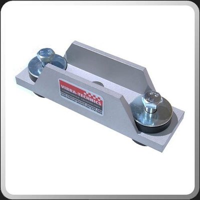
I will start by completely stripping the Voight box for inspection. I spent a lot of time taking casting flash off of the outside of the tail housing. Therefore I expect to find plenty of the same on the inside where nobody thinks the buyer will ever look. I will rebuild with a Quaife aluminum main case and top cover and adapt a Quaife short-throw gear lever. I think I can modify the Quaife lever to look exactly like the lever that Lotus installed on the +2 and therefore use the same boot. I will also make a more tidy mount to the chassis using the isolation mount from VibraTechnics (image below). This mount will give me more clearance to the frame (meaning less to trim from the frame). I will also be taking a hard look at the shift lever detent/travel limiting device that Voight installs in the top cover (now relocated to the tail housing). His parts are a bit agricultural in execution.
As for sailing, it has been a long time. I went through a youth sailing program when I was a kid and my father was pretty good at it. I still know to put my head down and how to work the jib sheets after I hear "ready about". I used to sail with a friend who had a very fine wooden hulled boat from the 1930s which he kept between Mystic and Groton, Connecticut. That was work, he insisted on winding the jib sheets into Flemish coils after tacking, even if we were going to tack again in 60 seconds. He also owned a DB4.
Russ Newton
Elan +2S (1971)
Elite S2 (1962)
Elan +2S (1971)
Elite S2 (1962)
-

CBUEB1771 - Coveted Fifth Gear

- Posts: 1546
- Joined: 09 Nov 2006
Hi Russ,
I do like the VibraTecnics mount. It looks like a more compact mount height wise. If this is the case, I am interested too. A little lower mount would give a little more wiggle room for the speedo angle drive.
The Mystic and Groton area is a great place to sail. I do Lightning class one design racing, but used to crew on an Ensign that sailed the Mystic to Groton area. Several fleets there and very picturesque. Some of the races went around Fishers Island. My friend Eric, an ex Elan racer (S1 with Brian Hart motor) has a really nice Brit Chance 41 that he sails out of Westport, CT. If interested, maybe we can do a Lotus group day sail?
Bill
- bill308
- Fourth Gear

- Posts: 736
- Joined: 27 May 2004
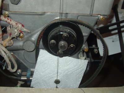
The engine crankshaft is now centered and the engine is at an acceptable height, so it?s back to the pedal box.
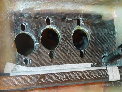
Initial fitment of the pedal box proved to be a little too high at the front panel and not quite horizontal side to side. Holes that were previously drilled for the master cylinders and pedal box through studs, needed to be slotted to get a better fit. Once everything was the way I wanted it, I added material to the foot well panel to clean things up. The first step was to glass in crescents at the tops of master cylinder through holes.
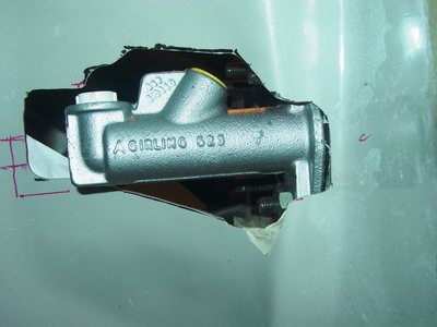
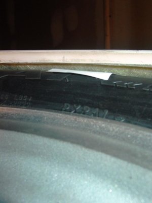
The next step was to reduce the slot sizes for the through studs to ensure positive placement of the pedal box. Reasonably tight holes assure the pedal box will go back into the proper position after paint. The last step was to trim the master cylinder holes so that there was clearance between the master cylinder boot and the sandwiched fiberglass panel. This was accomplished using sticky back paper over a length of aluminum tube I had lying around. Master cylinder boot fit into the steel bracket holes, either side of the foot well panel, is very tight on the clutch master cylinder. This end cylinder is supported by little more than half a crescent of the forward side steel doubbler plate. When the retaining nuts are tightened, this master cylinder cocks a few degrees, which I?d like to eliminate. I will try to build up the bed for the minimally supported side.
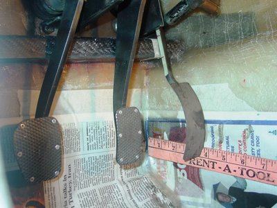
I?m not sure now if I need to notch the carbon fiber beam running under the bottom of the pedal box. I?m now thinking that it may be ok. Full depression of the accelerator pedal bottoms out on the beam face, about 3.75 inches from the face of the wheel well panel. The pedals on my S2 will depress more. Still, this may be acceptable as the pedals travel through a vertical plane before stopping. The push rod on the slave cylinder actually seems a little long, but without a clevis and pin on hand, I can?t tell for sure. It may need to be shortened. I?m also not sure what the full stroke measures on the master cylinders. I haven?t tried to fit the balance beam assemble yet and I?m not sure what the relationship should be between the brake pedal and the accelerator pedal heights, assuming heal/toeing is desirable.
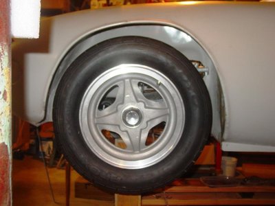
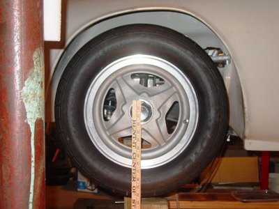
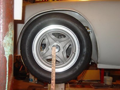
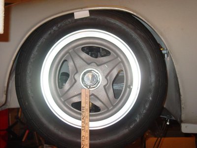
The other reason for addressing the pedal box and outer master cylinder at this time is to check clearance with the wheels and tires. To this end, I took delivery of a pair of Toyo RA1?s in a 205/60R13 size. I had 2 tires mounted on 26R Kelsport sourced, center lock wheels. These wheels are made of cast aluminum in classic 26R style. I don?t think they are particularly light or strong, but should be fine for a street car. I have open center, matching knock off spinners, also made of aluminum, somewhere in my inventory, but for now, the US style octagon nuts work for fitting purposes.
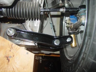
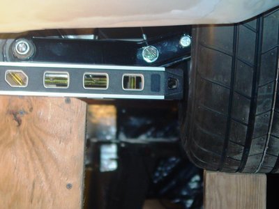
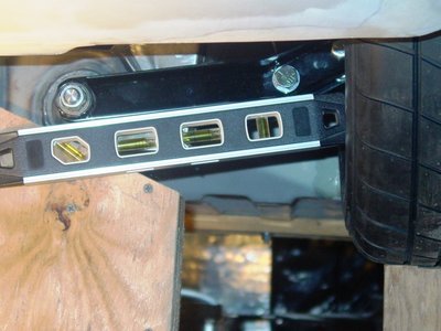
Initially, I set the ride height with the longest leg of the 26R lower front wishbones horizontal. This setting didn?t work with my wheel and tire combination. I then set the inner and outer lower wishbone pivots on a level line. That is the setting used for these pictures and I now believe it is correct. The previous setting left almost no room for bump travel. Even with this setting, wheel travel will have to be checked. All suspension geometry will have to be reset. The 26R lower wishbones are fixed in length, but the uppers are adjustable. The other thing is I?m having a replacement rack assembly rebuilt with new components. The special rack is ? inch shorter, which moves the inboard tie rod pivots ? inch more inboard per side, but minimizes bump steer effects over a much larger range of suspension travel.
You still have to set the rack height as usual, but toe change will be less or even eliminated altogether over a much larger range of travel than with the standard length rack. I expect the new rack to be shipped by DBE at the end of June.
- bill308
- Fourth Gear

- Posts: 736
- Joined: 27 May 2004
bill308 wrote:Initially, I set the ride height with the longest leg of the 26R lower front wishbones horizontal. This setting didn?t work with my wheel and tire combination.
Than you for your post. Would you elaborate on the rationale for your front wishbone setting? I believe the bent ones are for lowering the body, while keeping the neutral position (longest arm horizontal) symetrical up and down. If you want to keep the setting as pictured (higher body, i.e. outer holes aligned horizontally), would you not be better off with straight arms?
S4SE 36/8198
-

nmauduit - Coveted Fifth Gear

- Posts: 1998
- Joined: 02 Sep 2013
I second nmaudit on this. With the two mounting points -chassis and lower pivot-at the same heights there is no point in having 'cranked' arms. Especially concerned since I am considering fitting 26R lower A arms to my car to lower the front. However, I have height adjustable spring perches so do I need them? Anybody checked the geometry and can comment?
'65 S2 4844
- Davidb
- Fourth Gear

- Posts: 889
- Joined: 02 Jul 2009
Hi nmauduit and Davidb.
Thanks for your input. My rationale for the current setting is to allow room for tire bump travel. Both my front and rear spring purchases are adjustable for height so I have some latitude as to where I set them.
I think as long as the distance between the inboard and outboard pivot centers remains fixed, the shape of the in between member has does not affect wheel/tire geometry, only the travel range. For my case, there may not be an advantage with the cranked lowers. What the cranked lowers offer is a workaround for a front shock assembly that that may not compress enough at full bump. If the ride height is reduced at the front, a corresponding amount of shock travel is used up. The cranked design restores this ?used up? travel with a lower shock attachment point, nothing more IMHO.
How much suspension travel does one need? If one is racing on relatively smooth surfaces, probably not much travel is necessary or even desirable. I suspect suspension travel is very limited for this case? If one is driving on rough secondary roads, especially with pot holes and speed bumps, a lot more suspension travel and a higher ride height is likely desirable. It is my understanding, Colin et al, appreciated this and provided the Elan with generous suspension travel, modest spring rates, and firm damping. My plan is to strike a balance between the road/race applications, or at least provide a reasonably painless means of adjustment between them. To this end, I will fit TTR?s fast road setup, which is adjustable for height and damping. I?ve had a car set on the shelf for a number of years now, so it?s not likely the latest and greatest, but it should be an acceptable compromise and a good place to start and evaluate.
The question remains, how much bump and droop do I need? This will dictate the ride height to a large degree and the resulting geometry. Your further thoughts are appreciated.
Bill
- bill308
- Fourth Gear

- Posts: 736
- Joined: 27 May 2004
Bill, thanks for the response. Do you think that part of the problem may be using 205/60 tires? That is very wide for a street Elan. I use 175/70x13 on 6" rims and I find they are plenty wide enough and the diameter is the same as the original tires. (And they look fine). As regards suspension movement I would think 3" of bump should be more than enough...
Could I ask you to weigh one of the Kelsport 26R wheels you have? I would like to compare weights with the 6x13 Revolutions that I use. (9.25lbs).
Looking at the workshop manual illustration of the front suspension it is easy to see why Lotus chose the 'cranked' lower arms to lower the suspension. Are there any geometry geniuses out there who can tell if that is preferable to lowering the spring seat?
'65 S2 4844
- Davidb
- Fourth Gear

- Posts: 889
- Joined: 02 Jul 2009
bill308 wrote:Hi nmauduit and Davidb.
......
The question remains, how much bump and droop do I need? This will dictate the ride height to a large degree and the resulting geometry. Your further thoughts are appreciated.
Bill
A suspension expert I know who worked for Koni and who I used to race against told me that you need around 50 mm minimum bump and droop travel for a road going sports car to handle well on vary degrees of road smoothness and have an acceptable ride.
On a car designed for smooth racing tracks with a stiff suspension you could have less.
The Elan and Plus 2 in standard form had about 75mm
The standard Elan had
cheers
Rohan
-

rgh0 - Coveted Fifth Gear

- Posts: 8409
- Joined: 22 Sep 2003
Hi Davidb.
I just weighed one of my unmounted wheels on an old bathroom scale. This scale read 5 lbs with nothing on it and 17 lbs with the wheel weight, so 12 lbs +/- 1lb I?m guessing.
Yes, I think the tire size is an issue. My friend Eric runs this size on his ex-racer without issue. I do not know if he uses 26R lower wishbones as I do and I note his suspension is about as stiff as I would accept for street car.
Hi Rohan
Thanks for your input. Do you run 26R lowers?
What to do? Maybe I can set the suspension height to the level wishbone setting and live with the 1-7/8 bump travel. I guess I need to check first contact with the wheels/tires throughout the lock range and see what that looks like. I also need to look at both sides closely. I do prefer the look at the lower (level wishbone) ride height, but bump travel seems insufficient.
I could go with TTR recommended Avon tire in a 185/70R13 size or a smaller RA1 in a 185/60/R13 size? Other work arounds might be to look at moving the wheel/tire inboard ? inch per side by some means. Maybe adjustable lowers would allow me to bring the wheel/tire inboard to increase room for bump? I could set the front ride height to the horizontal pivot height which would give me 3 inches of travel before contact for road use. This setting is equivalent to the stock Elan ride height. A setting for occasional track use would be to set the long leg horizontal and dial up the damping, or maybe something in between?
- bill308
- Fourth Gear

- Posts: 736
- Joined: 27 May 2004
Hi Bill
I use the straight lower arms. But most of my lowering comes from running 175 / 60 x 13 tyres so i have sufficient travel of around 50mm with the TTR front shocks and 200 lb front springs. My Elan is drive-able on the road but really to hard for routine road use.
With higher profile tyres you need to have the cranked arms to lower the car and still have sufficient travel to bump in the shocks but you run up against to wheel clearance issues to the top inside of the of the wheel well. You will find that the wheel hits the body at full opposite lock with bump compression of the suspension with body roll. I find that even with my smaller tyres and have the cracks to prove it !
cheers
Rohan
-

rgh0 - Coveted Fifth Gear

- Posts: 8409
- Joined: 22 Sep 2003
Total Online:
Users browsing this forum: No registered users and 12 guests

