Bill's 26S
Hi Chris and Ian,
Thanks for your kind words and encouragement. Sorry for the late response.
I've been working on the balance beam pedal box I purchased from Kelvedon a couple of years ago and bonnet fitment issues. In this post we'll look at the bonnet fit.
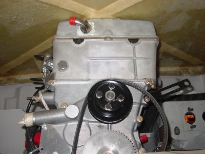
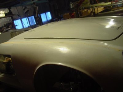
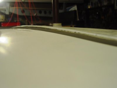
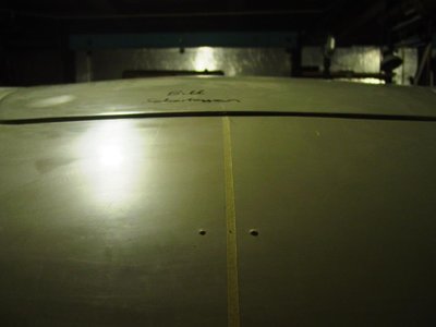
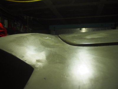
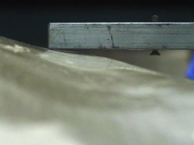
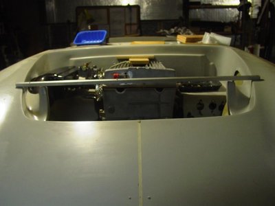
I finally got around to placing the bonnet on the body with the engine installed. I found the front of the cam cover prevented the bonnet surface from sitting flush with the surrounding body surface. Eventually, my friend Tim helped me fit a new TTR motor mount, as fitted to the exhaust side of the engine, but on the right side of the engine, like the Stromberg cars or like Spyder frames use. Just to be clear, I now have the same specification mount on both sides of the engine. This change dropped the carb side of the engine and cam cover down, about 1/2 inch. The back of the bonnet is now flush with the body surface, but the front of the bonnet still stands about 1/8 inch high. This is much better than it was, but I'd like to lower it at least 1/4 inch more. My choices include slotting the motor mounts themselves or the corresponding holes on the chassis, chamfer the top front edge of the cam cover, or shim the body up. A cursory look with one carb and the cold air box on, prior to the motor mount swap, showed I had over 1 inch clearance between the bottom of the air box and the top of the right side, horizontal foot well wall.
- Attachments
- bill308
- Fourth Gear

- Posts: 736
- Joined: 27 May 2004
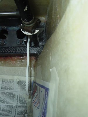
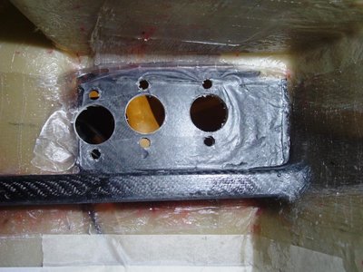
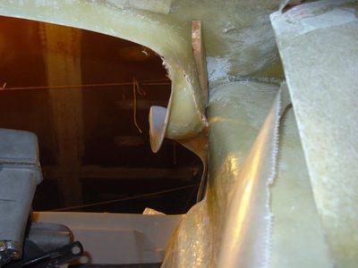
This post looks at fitting the Kelvedon LHD balance beam pedal assembly I purchased a couple of years ago. This pedal box mounts to the front and top walls of the left side foot well. My light weight body is very thin and all loads are resolved into fiberglass, so I reinforced the front, top, and 2 sidewalls with some unidirectional glass and resin. I also fabricated a 1 x 1.5 inch hollow, carbon fiber beam to reinforce the front wall, just below the pedal box. An attached pad continues under the front face of the pedal box. I then drilled the necessary holes in the front wall to accommodate the 6 studs on the front of the pedal box that anchor the front and retain the 3 master cylinders. It was difficult to determine just where these holes needed to be as the rear top of the pedal box needs to just kiss the top, horizontal panel where it is fixed by 2 additional bolts and the 6 studs prevent a simple hold in place and mark the stud holes. Bottom line, I'm close but there will need to be some adjustments and partial hole repairs.
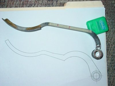
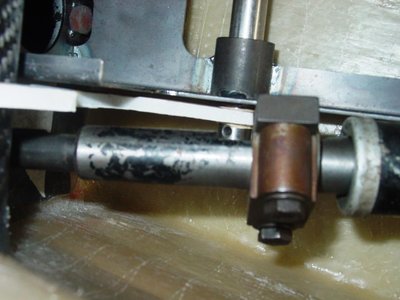
I was aware that the stem of the accelerator pedal was very close to the steering column. What I did not appreciate was the pedal stem being limited in throw buy the reinforcing beam, running just below the pedal box, The Kelvedon supplied accelerator pedal will not work with the reinforcing beam, so I now need to address issue.
I was aware that the stem of the accelerator pedal was very close to the steering column. What I did not appreciate was the pedal stem being limited in throw buy the reinforcing beam, running just below the pedal box, The Kelvedon supplied accelerator pedal will not work with the reinforcing beam, so I now need to address issue.
- Attachments
-
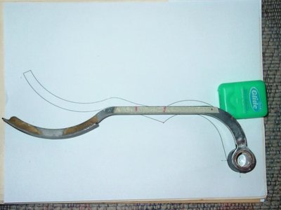
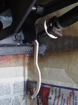
- The photo compares the installed geometries of the Kelvedon pedal and the new design pedal in the fully depressed position. Note the new pedal allows a lot more throw. The pedal stem curve near the pivot provides clearance for the steering column clamp. The steering column can puched forward about another inch from its current position.
- bill308
- Fourth Gear

- Posts: 736
- Joined: 27 May 2004
Hi Bill
Keep going ! I love that you are looking at all the possibilities so as to have a beautiful driver right out of the box .
I am making my brake box from scratch from stainless plate . It sits on top of the pedal box . when i figure out the picture taking end for the site i'll post some . I also vote for customizing the motor mounts as i'm making a new one for the drivers side to help clear the headers . I made a new dash, new gauges ,new heater motor ,leather and suede recovered seats , new exhaust and muffler , 26r chassis mods , and much more
well done with your progress
ian
- icarp
- New-tral
- Posts: 3
- Joined: 11 Nov 2016
Re the height of the front of the motor.
This has been covered somewhere on this site before but do check the spacers in the gearbox mount as this will have a dramatic effect.
I had much the same problem till I realised I did not have the whole drive line in alignment and the spacer was missing from the gear box mount.
This has been covered somewhere on this site before but do check the spacers in the gearbox mount as this will have a dramatic effect.
I had much the same problem till I realised I did not have the whole drive line in alignment and the spacer was missing from the gear box mount.
- Terry Posma
- Second Gear

- Posts: 95
- Joined: 24 Nov 2003
Hi Ian,
Thanks for the encouraging comments. I'd love to see photos of your build. DBE, TTR, and Kelsport all offer competition motor mounts that could be modified to suit my needs. I leaning toward the Kelsport offerings as they offer a larger bushing, so a softer "road" mount. A question in my mind is availability of replacement bushings when the "rubber deteriorates from oil/heat exposure.
Hi Terry,
I had a custom tranny mount fabricated to accommodate the T9 transmission. It is as high as possible to ensure the header/intermediate exhaust pipe is also as high as possible for road clearance. The bottom line is that the motor mounts need to lower the engine at least 1/4 inch at the motor mount location. This could be accomplished by slotting the motor mount holes but TTR heavy duty motor mounts don't have a lot of extra meat. The Kelsport mounts offer a softer elastomer because the bushing is bigger but replacement bushings are an issue. Also, the Kelsport motor mount on the exhaust side appears to do away with the normal spacer, not necessarily a bad thing.
I am also dealing with the height of the bonnet saddles. The left side saddle is too high. Some fiberglass work is in order. I need to lower the saddle about 1/4 inch to enable installation of the nylon bearing bolts. I determined this by applying clay to the saddle and pushing the bonnet down to the appropriate height. The resulting squished clay showed where the saddle was too high,
The new issue is the steering rack. It turns out the Spitfire rack length is not optimum. Replacement 26R specification racks were available from a couple of domestic suppliers. The actual resource was a guy local to me and it seems he is no longer supplying them. Spitfire racks are basically too long, meaning tie rods are too short, resulting in unnecessary bump steer. The 26R racks should be a little shorter, meaning the tie rods are a little longer. I have since ordered up a used Spitfire rack and had it sent to DBE for rebuilding. Ken Gray thought they had 26Rspecification racks in stock, but it turns out they did not. Research shows the rack should be 26 inches. I'm not sure how this compares with the Spitfire rack length at this time. If the ends of the tie rods fall on lines drawn on lines drawn between the inner pickups and outer ball joint/trunion, bump steer will be nil. In reality, the tie rod joints do not fall on these lines and are translated outboard of these lines. Improvements are possible. I'm trying to contact the supplier to get the details of his modification.
Bill
- bill308
- Fourth Gear

- Posts: 736
- Joined: 27 May 2004
The used Spitfire rack I purchased was sent to Dave Bean for rebuilding to Dave?s 26R specification. The way I understand it, this means the rack will be slightly shorter, moving the inner ball joints slightly inboard and minimizing bump steer effects. We are still trying to define exactly what the differences are as Dave is no longer with us and we have not yet found any notes documenting the changes. So, we are in a holding pattern on this.
This week I decided to address the bonnet fit issue. There are two problems; first, the front of the engine cam cover is too high. I plan to rectify this by purchasing a set of Kelvedon?s motor mounts that use silent block bushings. Specifically, I want the softer street version that uses a bigger bushing than the racing version, resulting in less vibration being transmitted from the engine block to the chassis. I will likely have to fabricate new pieces from the chassis motor mount to the silent block to lower the engine about 1/4 inch at this point. I believe these new pieces will be made of probably 0.090 inch mild steel. The concern for me is that replacement bushings need to be available and I haven?t gotten an answer on this yet.
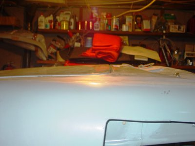
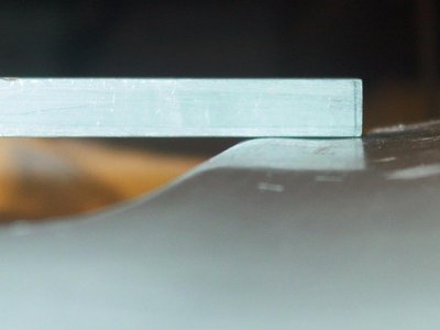
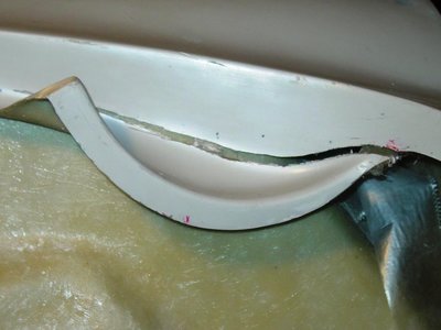
The other bonnet fitment issue is the left (port) side saddle is too high. I cut a slit along the saddle?s vertical wall and forced the front of the saddle down until there was a 1/4 inch gap at the center of the cut. The center of the cut was then tack bonded and after curing, I forced the front of the cut up to reduce the gap from about 3/8 inch to about 1/4 inch and tack bonded it. Follow on surgery will finish the back side bonding and after curing, I will prep the front side with a carbide ball cutter in a die grinder for strip bonding and finishing.
- Attachments
- bill308
- Fourth Gear

- Posts: 736
- Joined: 27 May 2004
Every little detail ! good on you Bill. I think you are having fun.
My motor left mount will be abit more changed than most , i am cutting the mount off of the chassis
and moving it forward about 3/4 inch and the angle will go forward instead of rearward .
This gives me ample room for custom headers . I will still use the stock engine mount .
I will fab up a plate for the block , then stock mount to new chassis point
I am in the midst of selling my house so elan work is mostly in my head
keep at it
Ian
- icarp
- New-tral
- Posts: 3
- Joined: 11 Nov 2016
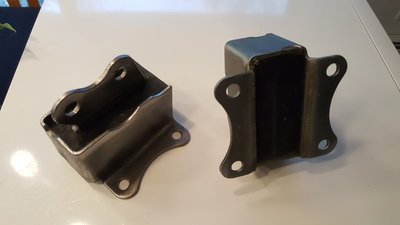
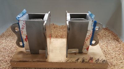
Bill, I also bought a set of Kelvendon's motor mounts (still have them if you want to check them out in person) but decided to use the standard motor mount metal pieces and pour my own urethane. Pretty easy. They're holding the BDG up and in the spot I wanted but still haven't started the engine so I can't swear that they'll hold up. Several durometers of urethane and the appropriate primer available from McMaster Carr.
TomR
TomR
- TomR
- Second Gear

- Posts: 116
- Joined: 19 Sep 2003
Hi Tom,
I hadn't considered fabricating stock looking mounts as you show, but that appears to be a real option. Are the mounts you purchased from Kelvedon the race or fast road versions?
Doug, at Kelvedon, tells me the softer, fast road motor mounts, use the silent blocks from the rear inner A-arm pickups. This bushing is bigger, therefore softer then their race mount, all else being the same.
Yes, I'd very much like to check them out in person.
Bill
- bill308
- Fourth Gear

- Posts: 736
- Joined: 27 May 2004
Bill,
I believe I have two sets of each of the Kelvedon small and large metaplastic bush types. Long story, I was trying to use them in the +2 which uses the same height mounts on both sides of the engine. I bought the small bush type and six months later they came out with the large bush style! I'll be happy to send one set of each to you for evaluation.
Russ
Russ Newton
Elan +2S (1971)
Elite S2 (1962)
Elan +2S (1971)
Elite S2 (1962)
-

CBUEB1771 - Coveted Fifth Gear

- Posts: 1546
- Joined: 09 Nov 2006
Bill,
I just ran across this site:
http://www.vibra-technics.co.uk/ford/cortina_mk1
Very interesting, especially the gearbox mount that could be easily adapted to the Elan chassis. The engine mounts would require an entirely new bracket for attachment to the chassis.
Russ
I just ran across this site:
http://www.vibra-technics.co.uk/ford/cortina_mk1
Very interesting, especially the gearbox mount that could be easily adapted to the Elan chassis. The engine mounts would require an entirely new bracket for attachment to the chassis.
Russ
Russ Newton
Elan +2S (1971)
Elite S2 (1962)
Elan +2S (1971)
Elite S2 (1962)
-

CBUEB1771 - Coveted Fifth Gear

- Posts: 1546
- Joined: 09 Nov 2006
Hi Russ,
Is it just the bushes you bought from Kelvedon, or mounts plus bushes? The larger bushes are from the rear inner A-arm mounts. Do you know the source for the smaller, stiffer mounts, maybe the inner front bushes?
The vibra-technics offerings are interesting and appear to be workable alternatives, but pricey.
TomR fabricated motor mounts using a urethane elastomer. I'm thinking that this could offer a viable alternative to the standard silent block bushes if a harder or softer durometer is desirable. The urethane may also be more oil and/or heat resistant.
Bill
- bill308
- Fourth Gear

- Posts: 736
- Joined: 27 May 2004
Bill,
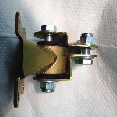
I bought the complete engine mounts kits from Kelvedon. It has been a while since I did the trial fit but I recall that I was worried about the large bush version. The tube on the engine side bracket (which houses the bushing) has such a large OD that it could easily touch the chassis side bracket under very minor deflection. I just edited to attach a photo of the Kelvedon large bush style. You can see what mean about the clearance between the two brackets.
Russ
Russ Newton
Elan +2S (1971)
Elite S2 (1962)
Elan +2S (1971)
Elite S2 (1962)
-

CBUEB1771 - Coveted Fifth Gear

- Posts: 1546
- Joined: 09 Nov 2006
Hi Russ,
Thanks for the photo. Not a lot of shake space there. I guess I'd like to see about 0.050 inch clearance or more. I expect most deflection would be radial, about the crank centerline. Still, side to side deflection could be an issue. If necessary, a relief might be ground in for additional shake space.
Do I understand correctly that you bought 2 sets (1 set includes L & R sides) of race and 2 sets ( 1set includes L & R sides) street mounts, for a total of 4 complete sets, enough for 4 cars?
Bill
- bill308
- Fourth Gear

- Posts: 736
- Joined: 27 May 2004
Bill,
Yes I have four car sets. I thought that I would need two Elan sets to make one +2 set, however there are additional asymmetries in the chassis-side brakes that make this a bit complicated. Such is life, I have a ton of parts and no running cars!
Yes I have four car sets. I thought that I would need two Elan sets to make one +2 set, however there are additional asymmetries in the chassis-side brakes that make this a bit complicated. Such is life, I have a ton of parts and no running cars!
Russ Newton
Elan +2S (1971)
Elite S2 (1962)
Elan +2S (1971)
Elite S2 (1962)
-

CBUEB1771 - Coveted Fifth Gear

- Posts: 1546
- Joined: 09 Nov 2006
Total Online:
Users browsing this forum: No registered users and 25 guests

