Bill's 26S
Hi Eric.
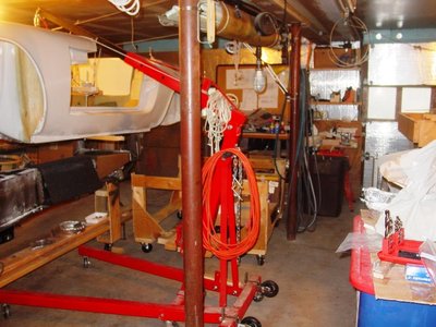
After much work, I now have the body centered on the engine/chassis and I'm in the process of drilling and tapping holes where necessary.
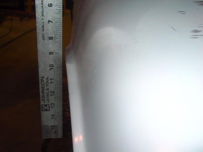
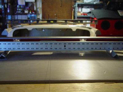
Initially, I couldn't get the body over to starboard enough as it was constrained by a section of the tunnel contacting the chassis. The rear starboard suspension turret cavity in the body was not square on the top and this was again preventing the body from being centered. A 5/16 inch slit along the top horizontal corner and reglass of this portion of the tunnel and reshaping/glassing of the turret cavity (a tricky 3-wall intersection) allowed centering of the body on the chassis. The body is now centered with respect to the wheel arch lips to the chassis centerline.
I am interested in your seat frames and hardtop and I'm looking forward to another ride in your street racer Elan, if this rain ever stops.
Yesterday we put the docks in at NBYC, about a 3-hour ordeal, but finished before it the latest storm hit. I'm desperately trying to get my boat ready for the racing season and also look forward to doing some sailing on your boat.
Feel free to stop by anytime and view the progress on my car.
Bill
- bill308
- Fourth Gear

- Posts: 736
- Joined: 27 May 2004
All body/chassis holes are now drilled to size and tapped where necessary. The two bobbins adjacent to the rear turrets were drilled for 3/8 inch bolts, so I had to drill them out for the correct 7/16 inch bolts. Thru bolt holes were first drilled with a 1/4 inch bit. I used a 2 inch length of 5/16 inch OD US brake line to protect the 3/8 inch threaded bobbins during the drilling process. This worked well for alignment and protection functions. I used a special bushing to align the rear turret drillings as these were larger in diameter. The bobbin hole was increased in size to 7/16 inch prior to tapping and the corresponding turret holes were drilled with a Q size bit prior to tapping to 7/16 UNF. The four holes tapped for 3/8 UNF were drilled with a 5/16 drill before tapping. Thru holes in the flange were enlarged to 3/8 inch after the body was removed using a step drill bit. All tapped holes were tapped with the body in place.
The port, front turret required three 1/8 inch shims and the starboard front turret required one 1/16 inch shim to center the body relative wheel arch lips and center of the chassis. Additionally, the port rack mount required one 1/8 inch shim and the starboard rack mount required one 1/8 inch and one 1/16 inch shim. All shims were aluminum plates with shapes matching the respective mating surfaces.
The body was removed to bring the thru bolt holes to 3/8 inch size and allow other operations.
With the body off it was now time to take a hard look at fitting the exhaust system. The early look showed the TTR system would work with some fetteling. Now it became clear that the 2.25 inch OD exhaust pipe really needs to be higher in the gearbox location for better ground clearance. It appears that a combination of remedial changes will be required.
1. The Voights conversion case has a feature on the bottom of its case that limits how high the pipe can be mounted. Does anybody know if this lug can be shaped or cut off without exposing any internal pieces or a hole?
2. There is a similar limit on the Quaife case, but not as bad.
3. It may be necessary to also dimple the pipe to increase clearance.
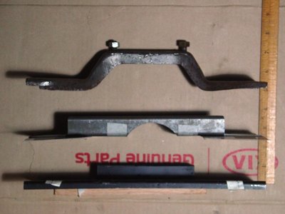
4. The standard Voights tranny mount runs straight across the bottom of the chassis flanges. I obtained a replacement bridge type motor mount on Ebay, reportedly for a 26R, that I now have in place, but it will have to be modified as it is too high by about 5/8 inch. This looks like a cut and weld modification, but the bolt holes are pretty close to those I used for the Voights mount, so that is a good thing as the flange uses captured nut inserts.
Bill
- Attachments
- bill308
- Fourth Gear

- Posts: 736
- Joined: 27 May 2004
The last few weeks I've been trying to perfect the exhaust system with the goal of getting it as high as possible for the best possible ground clearance. The car will be running a little bit lower with the 26R front suspension so adequate ground clearance on Connecticut roads is important.
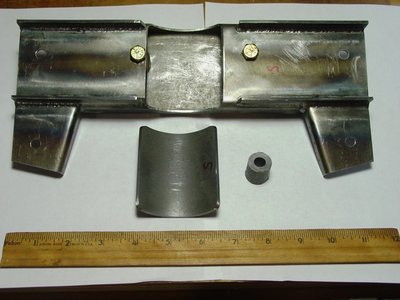
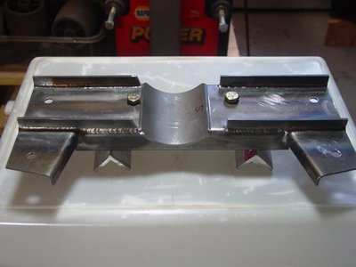
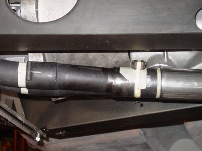
I'm using the TTR extra large bore header and exhaust system. The mild steel collector has a 2 inch od and the stainless steel intermediate pipe has a 2.25 inch od and is 18 gauge (0.050 wall). I was going to use the TTR intermediate pipe but the hockey stick bend was not quite right for the T9 tranny with Voights conversion, so I a sourced a tube and U-bend from Burns Stainless. I made a tricky cut on the U-bend giving a 15 degree bend and had it butt welded to the tube by a local aerospace welder using a MIG process with Argon gas. It turned out well. The other issue required a modification of the angle of the collector so that all the tubes were on the same plane. This allowed the top of the collector and the intermediate pipe to run above the bottom of the chassis surface resulting in pretty good ground clearance for these large diameter tubes. Of course the Quaife case and Voights case and adapter required reliefs to accommodate the high position. The casting feature on the bottom of the Voights case was cut off with a hack saw and an additional crescent relief was cut with a die grinder and a large oval shaped carbide burr. Lots of material was removed. A smaller amount of material was removed from the bottom of the Quaife case. The high exhaust system means the Voights tranny mount won't work, nor will a 26R mount I sourced on Ebay, so I am now fabricating a new tranny mount which I will document in my next post.
I'm using the TTR extra large bore header and exhaust system. The mild steel collector has a 2 inch od and the stainless steel intermediate pipe has a 2.25 inch od and is 18 gauge (0.050 wall). I was going to use the TTR intermediate pipe but the hockey stick bend was not quite right for the T9 tranny with Voights conversion, so I a sourced a tube and U-bend from Burns Stainless. I made a tricky cut on the U-bend giving a 15 degree bend and had it butt welded to the tube by a local aerospace welder using a MIG process with Argon gas. It turned out well. The other issue required a modification of the angle of the collector so that all the tubes were on the same plane. This allowed the top of the collector and the intermediate pipe to run above the bottom of the chassis surface resulting in pretty good ground clearance for these large diameter tubes. Of course the Quaife case and Voights case and adapter required reliefs to accommodate the high position. The casting feature on the bottom of the Voights case was cut off with a hack saw and an additional crescent relief was cut with a die grinder and a large oval shaped carbide burr. Lots of material was removed. A smaller amount of material was removed from the bottom of the Quaife case. The high exhaust system means the Voights tranny mount won't work, nor will a 26R mount I sourced on Ebay, so I am now fabricating a new tranny mount which I will document in my next post.
- Attachments
-
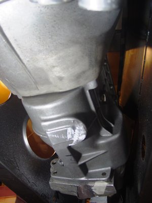
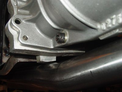
- This photo shows the minor clearance relief cut in the Quaife case and the more significant cut made in the Voights case and adaptor plate. The collector pipe and intermediate meet at the Quaife case relief and the hockey stick bend and butt weld are positioned at the Voights case and adaptor relief cut.
-
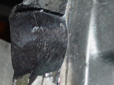
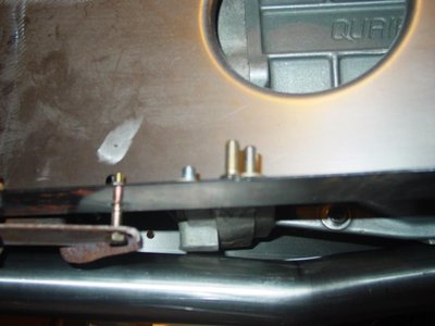
- This photo shows the Voights case where the casting lug was. A large amount of aluminum was removed to create the crescent reliefs in the Voights case and adjacent adaptor plate. The intermediate pipe hockey stick bend and butt weld are located here. There is still a little cosmetic clean up to do, but I did not punch through into the interior. This cut was hard labor.
-
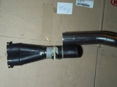
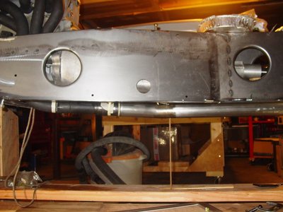
- The Y-pipe with collector and the intermediate pipe with the hockey stick bend, that was butt welded on, are shown. Note the overlap and O2 sensor bung location. The Y-pipe vertical deflection was eliminated by cutting out a pie shaped wedge where the 2 manifold tubes meet the collector. I cut 95% of the way through the weld and the adjacent collector pipe, then bent the pipe to close the opening, where it was welded.
-
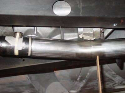
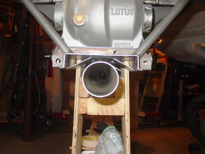
- This picture shows the end of the collector and intermediate pipe in their proper location. An O2 sensor bung is taped in place where I need to drill a hole, weld the bung on, then remove any protruding metal in the gas flow path. The intersection of the collector and intermediate pipe is at the location of the Quaife case relief. The vertical wood support is at the Voights case and adaptor, where the casting feature was removed and a crescent relieve was cut.
Last edited by bill308 on Tue Jul 25, 2017 10:50 pm, edited 1 time in total.
- bill308
- Fourth Gear

- Posts: 736
- Joined: 27 May 2004
Hi Davidb,
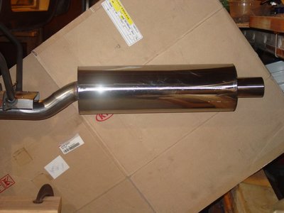
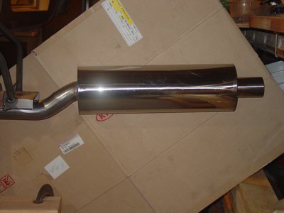
Except for the intermediate pipe, it's all largest bore TTR components to accommodate 8k+ rpm and 1730 cc's. Specifically, the muffler is TTREX 009. I believe the exhaust manifold is extra large bore and high ground clearance TTREX 111 and the pipe was the matching TTREX 010. The Y-pipe collector required surgery to make the tubes run on a flat plane, but the angle on the intermediate pipe was not quite right and I really couldn't reliably change it, so I built my own.
Bill
- bill308
- Fourth Gear

- Posts: 736
- Joined: 27 May 2004
I also have a 1720 engine with 2" main pipe- I fitted one of these Dynomax 17676 mufflers: http://www.dynomax.com/super-turbo-offs ... -side.html
Despite its size it fits quite well and I have yet to have it ground out, despite going over some sizable speed bumps to test it.
However, I am finding the exhaust too noisy and I have ordered some "Accousti-Fill (sp?) to stuff it with. This will mean cutting one side off, filling the muffler body and re-welding the side back on.
'65 S2 4844
- Davidb
- Fourth Gear

- Posts: 889
- Joined: 02 Jul 2009
Hi Davidb,
Years ago, I found a major source of exhaust noise on my S2 SE to be the boot floor vibrating. During a repaint at the time, I stripped all the tar like undercoating. The undercoating provided a damping effect on the panel surrounding the original muffler and when removed, allowed the panel to vibrate more aggressively or amplify the sound. You might want to considersound deadening material bonded to the inside and/or outside of the boot floor, especially close to the muffler, before cutting your muffler apart. I'm thinking Dynamat for the cockpit and boot floors and tunnel. I'll try installation just on the interior to start with. If I need more I'll add it to selected areas of the exterior.
Bill
- bill308
- Fourth Gear

- Posts: 736
- Joined: 27 May 2004
This modification works really well to reduce noise inside the car. 
I did this on my S3 when I had the differential out but is even easier with the body off.
lotus-gearbox-f37/sound-proofing-the-differential-t26887.html
I did this on my S3 when I had the differential out but is even easier with the body off.
lotus-gearbox-f37/sound-proofing-the-differential-t26887.html
67 Elan Super Safety
67 Elan +2
67 Elan +2
- seniorchristo
- Fourth Gear

- Posts: 590
- Joined: 19 Dec 2013
Thanks gentlemen-I didn't mean to co-opt Bill's thread!
Bill, I too had concluded that the boot/trunk floor must be contributing to the noise-I do not carry a spare wheel and so I have been packing the floor with anything that will absorb noise. I may try Dynamat.
Seniorchristo, I had the body off the chassis for a year until March! I suspect that the same result can be obtained by lifting the carpet and gluing a dense substance to the area above the diff?
'65 S2 4844
- Davidb
- Fourth Gear

- Posts: 889
- Joined: 02 Jul 2009
Hi Chris,
If I understand correctly, you are advocating capping the frame, in the area of the final drive, with a sound absorbing panel?
Hi Chris, you are suggesting adding sound damping material under the carpet, in the same area, as an alternative?
I wonder if noise control in this area can be combined with a final drive cooling solution? Maybe a sound absorbing, conformal shroud that will channel cooling air to the surface of the final drive casing? Air could be sourced by the traditional 26R side scoop or maybe a high quality muffin fan, as found in air cooled aviation/military electronics? Just channel the air flow with sound absorbing material?
Bill
- bill308
- Fourth Gear

- Posts: 736
- Joined: 27 May 2004
The exhaust system is now nearly finished and the rear tranny mount is now complete (less paint) and is trial fitted.
Bill
Bill
- Attachments
- bill308
- Fourth Gear

- Posts: 736
- Joined: 27 May 2004
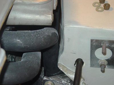
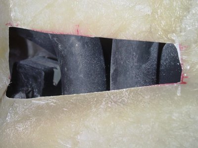
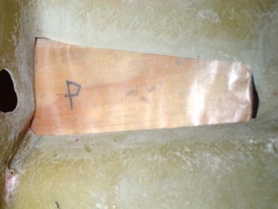
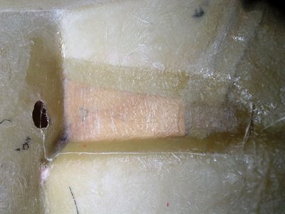
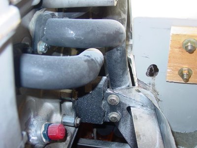
The nest issue to be addressed was clearance between the large bore headers and the driver side foot well. Because of asymmetry or distortion of the body, the body had to be moved as far right as possible to center the wheel arches. This reduced the clearance between the header tubes and the driver side foot well to nothing. The solution was to remove a fiberglass bulge in the inner foot well with a replacement flat wall. This will allow an aluminum sheet radiation shield with 2 side air circulation to be fitted. The shield will be mounted on stainless (low thermal conductivity) standoffs midway between the foot well fiberglass wall and the header tubes.
- Attachments
- bill308
- Fourth Gear

- Posts: 736
- Joined: 27 May 2004
Nice work Bill! Great to see your progress! 
67 Elan Super Safety
67 Elan +2
67 Elan +2
- seniorchristo
- Fourth Gear

- Posts: 590
- Joined: 19 Dec 2013
Total Online:
Users browsing this forum: No registered users and 12 guests


