Bill's 26S
Hi nmauduit and Rohan.
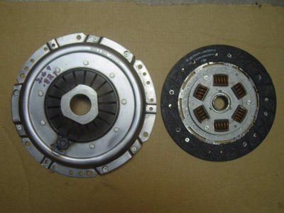
Thanks for the feedback on the clutch issue. Yesterday, I called Ken at DBE and ordered a replacement clutch cover as they had come in on Tuesday. My engine builder, MWE, would have used a version of this clutch for the dyno runs, so I suspect it will be ok for a street car with the friction disc supplied by Voights. This assumption could come back to bite me, but it's time to move on.
Today, I ordered up a set of the bush adapters, with metalastic bushes installed, from Spydercars. This will be an interesting experiment. I was not comfortable with rod ends as I've never used them before and they are not normally used on a street application. Loads on the upper front wishbones should be modest and certainly less than the (fixed) lowers because of upright geometry.
Bill
- bill308
- Fourth Gear

- Posts: 736
- Joined: 27 May 2004
bill308 wrote:Hi nmauduit and Rohan.
Thanks for the feedback on the clutch issue. Yesterday, I called Ken at DBE and ordered a replacement clutch cover as they had come in on Tuesday. My engine builder, MWE, would have used a version of this clutch for the dyno runs, so I suspect it will be ok for a street car with the friction disc supplied by Voights. This assumption could come back to bite me, but it's time to move on.
Today, I ordered up a set of the bush adapters, with metalastic bushes installed, from Spydercars. This will be an interesting experiment. I was not comfortable with rod ends as I've never used them before and they are not normally used on a street application. Loads on the upper front wishbones should be modest and certainly less than the (fixed) lowers because of upright geometry.
Bill
Hi Bill,
I am contemplating the use of these bush adapters on the rear of my Elan which has TTR adjustable wishbones with rod ends. I will be interested in your views so hurry up and get your car on the road
Later
Chris
67 Elan Super Safety
67 Elan +2
67 Elan +2
- seniorchristo
- Fourth Gear

- Posts: 590
- Joined: 19 Dec 2013
Hi Chris.
Please let me know if I'm not working fast enough for you.
I notice John Worzel posted some adjustable rear A-arms that are fitted with similar bush carriers. The other thing I like about John's setup is one of the adjustable links appears to slide within it's tube so can be adjusted by tightening 2-pinch nuts. Very cool. I wish I had front upper wishbones that could do this, but I've bit off enough to chew for now. Without this sliding feature, which is a bit bulky, one has to break free one of the A-arms or the bushing and twist to change the length. In addition to being inconvenient, one is limited to either 1/2 or 1 full turn increments, depending on whether the bushing carrier or the wishbone is turned.
The replacement clutch cover came in late last week and I brought it down to the machine shop for balancing. The original clutch cover I purchased (also 170 lb ft specification) was I finger type and I needed one with a bearing platform. Ken, at DBE sent it priority mail, $13 coast to coast, not bad. The outer box was damaged, but the inner box and most importantly the clutch cover was fine. The new clutch is a Borg and Beck.
I have one more set of measurements to make to ensure the clutch engagement is acceptable and I need the clutch cover and friction plate installed on the flywheel and mounted on the crank. The slave cylinder needs to be depressed 9-9.5 mm (0.354-0.374 inches) minimum when installed to ensure sufficient depression to disengage the clutch, otherwise the concentric slave cylinder needs to be shimmed out.
Bill
- bill308
- Fourth Gear

- Posts: 736
- Joined: 27 May 2004
The clutch plate came back from balancing. It was out 3.69 g and was balanced to 0.821 g.
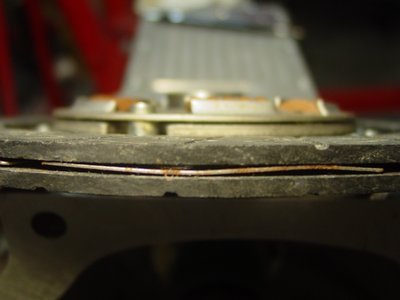
When I fitted the clutch with driven plate to the engine crank to get the distance of the throw out bearing platform fromt the back of the block, I had difficulty getting a consistent reading. It turns out the friction surface overall thickness was no longer uniform. Having been stored for so long, rust had developed on the supporting plate between the friction surfaces. I no longer feel comfortable fitting this driven plate.
So now I need to find a replacement driven plate. Burton Power lists several AP Racing
CP5354-38 a 4-paddle plate with cerametallic facings and springs
CP3532-5 a conventional type with non backed organic facings and springs
CP3531-1 a conventional type with steel backed organic facings and springs
and 3 Helix offerings
76-1518 a 4-paddle plate with cerametallic facings and springs
70-1518 a conventional type with metal backed organic facings and springs
I'm leaning toward the CP3531-1. The cerametallic facings are probably best for track use but would probably wear the flywheel face more aggressively because of the facing hardness, but I don't know for sure. I sent an inquiry to Burton Power to see which they recommend for my application.
I need to fit the driven plate to get a good measurement of the bearing platform distance as I think I need to shim out the coaxial throw out bearing assembly. Voights calls for a compression of 9-9.5 mm (0.354-0.374 inches) when fitted.
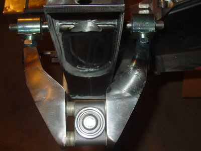
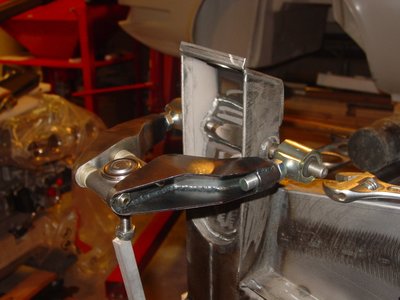
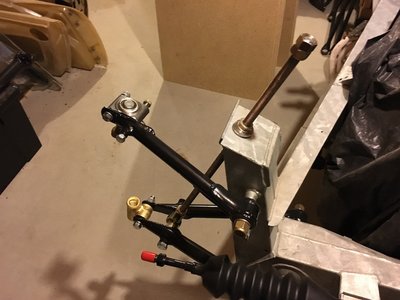
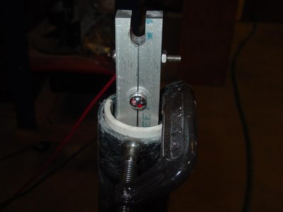
The bushing carriers came in from Spyder and I think they look pretty good. I fitted them up to the upper 26R wishbones and then mounted one set to the chassis with a ball joint to see how they fit. Note the washer spacers to add caster, lite built into the early S1 and S2 cars.
Bill
- bill308
- Fourth Gear

- Posts: 736
- Joined: 27 May 2004
Burtons Power did not respond to my email requesting their recommendation for a driven plate, so I ordered their AP Racing CP5351-1, with a steel backed organic facing, rather than the paddle type with ceramic facing, which I fear would wear the flywheel lining too much..
To set initial caster and camber, I ordered a Johnson 1886-0200 angle finder. This device is accurate to 0.1 degree, so setting caster to negative 4-degrees and camber to negative 1-degree is simplified. I will use a 7/16-inch rod in place of the front upright for the initial setting. This device is accurate to 0.1 degree. Please see:
https://www.zoro.com/johnson-digital-an ... +1886+0200
I inserted a 7/16 rod of the appropriate length into the upright position. I will use this rod for the initial caster/camber measurements.
Bill
- bill308
- Fourth Gear

- Posts: 736
- Joined: 27 May 2004
bill308 wrote: inserted a 7/16 rod of the appropriate length into the upright position. I will use this rod for the initial caster/camber measurements.
Bill,
I made up a pair of links to be used in place of the front spring/damper units for assembly and setup of the front suspension. I use 1/2-20 threaded rod with a 1/2" female rod end for attachment to the lower control arms. I also use a pair of spherical washer sets where the threaded rod passes through the top of the chassis towers. Your could use something like this to check caster, camber and toe changes throughout the travel from full bump to full droop.
Russ
Russ Newton
Elan +2S (1971)
Elite S2 (1962)
Elan +2S (1971)
Elite S2 (1962)
-

CBUEB1771 - Coveted Fifth Gear

- Posts: 1546
- Joined: 09 Nov 2006
Hi Russ.
Thanks for your last post. Tim Marx recommended a similar setup. I will implement a simplified version. I'll use a 1/4-inch threaded rod with an eyebolt extension, in lieu of your larger threaded rod with precision rod ends. A series of nuts, jammed together, for a full bounce, neutral, and rebound level, will be fitted. A C-clip at the upper shock mount will enable quick a quick change of height adjustment.
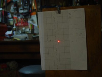
The plan is to set initial caster and camber, before fitting the body to the chassis. The previously described angle finder is on order and should be in before the end of the week. Bump steer setting is a little different. I'm hoping 3-discrete heights will enable a pretty good dial in. I believe the object is to minimize toe change over the suspension travel. I think I need some sort of laser pointer, with a V-groove and magnetic base, to attach to the either the upright or the axle. The laser pointer then projects a (small) spot on a screen or plain. Plotting the 3-discrete settings and their associated laser spot projections, constitutes the evaluation method. Anybody know of a suitable laser pointer? The pointer should have a V-groove, a magnetic retention feature, and a reasonably fine illumination point.
I'm still waiting on the clutch driven plate from Burton Power and an ebay AM 2300/01 ammeter. I still need an FG 232530/71 fuel gauge to match the sender in my new tank. The steering arm I was missing came in from James Paddock, Ltd in the UK.
Bill
- bill308
- Fourth Gear

- Posts: 736
- Joined: 27 May 2004
There has been some slow progress.
The engine and transmission have mated with the clutch package. All dimension checks are complete and the coaxial slave cylinder is spaced acceptably. There will be a 9-10 mm depression of the slave assembly at rest. Voights? clutch kit calls for 9-9.5 mm depression, so ok to go. Separation of the engine/tranny is still necessary, as the slave pressure and bleed lines need to be plumbed. A couple of pilot holes were drilled in the bell housing to locate the emergence of the slave bleed line from the bell housing. The line will terminate at a custom bracket at the number 4 exhaust branch flange bracket. Voights version of this bracket is not suitable as my exhaust primary tubes are now bigger and the bracket holding the bleed nipple needs to be clocked higher to avoid interference with the #4 exhaust tube.
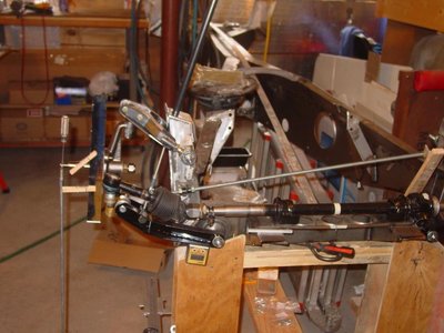
The front suspension wishbones and uprights are fitted with temporary fasteners and not fully tightened. The front suspension is set for 0.8 degree (negative) camber and 4 degrees caster. There is about a 1-degree mismatch between the wishbone end bushing axes and the mounting stud axis. This mismatch is taken up by the standard metalastic bushing. So the rubber is distorted on both ends of the bushings because the rotational axis is not the same for the front and rear wishbones . Normally this misalignment is not happen on the race application, because a rod end bushing has extra degrees of freedom so doesn?t introduce a bending element onto the inner suspension studs. IMHO it would be much better if the angle of the 26R wishbone, ? inch female thread tapings, were on parallel axes. I have since obtained a set of special upper wishbones with the inboard threaded sleeves only tack welded to the A-arms. This will allow me to set the angel properly for my application prior to welding.
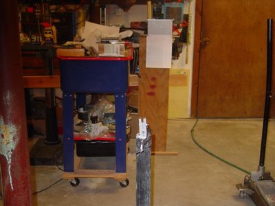
The steering rack is now in position side-to-side, but the rack platforms need to be shimmed just shy of 0.200 inches thick. Using a laser pointer, I set up an alignment rig to measure toe change. I found that platform height changes of 0.001 inches have a measureable impact on bump steer.
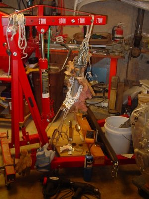
The strut/bearing carriers were soaked for 3-days in a rust dissolver. The steel strut tube had surface rust that would be an issue during disassembly, because of the 0.002 inch interference fit between the aluminum casting and the strut tube. The separation plan is to thoroughly de-rust (done) then protect with a coat of Rust Buster penetrant spray (done).
I was thinking separation would require heating the bearing carrier to 300F, then chilling the steel tube with liquid nitrogen at -320F, or dry ice at -109F (piss poor contact conductance of the solid pellets with the tube id means ineffective cooling), or liquid CO2 at ? 70F (siphon or inverted CO2 tank).
The steel tube od: is 2 inches. I?m told the interference fit with the bearing carrier casting is 0.002 inches. Wheel bearing bores are also suspect. I?m told the bearing should have a 0.001 inch interference fit with the aluminum casting. It?s unlikely the bearings were only changed at temperature, so the actual interference fit on used parts is probably insufficient from my project.
Ultimately, I was unable to separate the tube and bearing carrier using dry ice to chill the tube and heating the bearing carrier with a heat gun. I limited the bearing carrier to about 300F as I did not know how hot I could get it without causing metallurgical changes. A later conversation with John Stowe, who owns a local foundry and did DBE?s Twincam head design and also many of the BDA head castings sold by others, indicated silicone aluminum alloys (like LM4) have an ageing temperature of about 310F. Going above this temperature allows the constituents to become mobile in a solid solution, ruining any heat treatment. So, separation is easier at higher temperatures, but the aluminum properties are degraded.
In the end, I ordered a set of adjustable struts from TTR.
Bill
Last edited by bill308 on Sun Apr 30, 2017 9:57 pm, edited 2 times in total.
- bill308
- Fourth Gear

- Posts: 736
- Joined: 27 May 2004
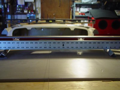
Bill, This is a great story. I may have missed it but did you measure the rack mount height from a straight edge placed across the upper suspension pivots? I think it is the standard method-I would be interested to hear what yours measures- thanks.
'65 S2 4844
- Davidb
- Fourth Gear

- Posts: 889
- Joined: 02 Jul 2009
Hi David,
Yes I did the measurement as recommended by Brian Buckland and found it to be close, but not quite right for my chassis. I think this is just an approximation.
As it sits, I'm getting about an 0.15 inch (1.9 cm) beam deflection at the target,10 feet in front to the chassis, over the hub travel range of 3.5 cm bump to -2.0 cm droop from a horizontal lower wishbone (TTR's recommendation). This works out to about 0.22 mm deflection at the wheel rim edge (about 7 inch radius), where TTR calls for 0.2 mm, with all error on the toe-in side. I can get it better, but upper front wishbones are to be replaced and even the chassis paint thickness (now bare steel) will have a measureable affect, so I'll have to do this again during final assembly. I'm good enough now for a trial assembly.
Bill
- bill308
- Fourth Gear

- Posts: 736
- Joined: 27 May 2004
Bill
Glad to see you're making some progress with your 26S. Now quit being so precise and just get er done You can do the fine tuning later. I would like to see some road action when I visit Connecticut this summer! Keep up the good work.
Chris
Glad to see you're making some progress with your 26S. Now quit being so precise and just get er done
Chris
67 Elan Super Safety
67 Elan +2
67 Elan +2
- seniorchristo
- Fourth Gear

- Posts: 590
- Joined: 19 Dec 2013
Hi Davidb and Chris, thanks for the advice. 
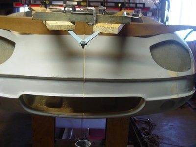
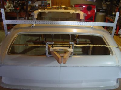
The center line for the chassis was established based upon the inboard suspension pickup points. The vacuum tap on front tank was confirmed centered and a V-notch was filed into the back edge of the chassis to establish a rear center point.
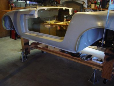
The chassis. with engine installed with headers, was leveled on the bespoke dolly and then the body was dropped onto the chassis.
Establishing the center of the body was difficult. There were two choices, find the center of the major features like the grill, the engine bay opening, and the boot, or go with the front and rear wheel arch lips. In the end, I decided to key on the wheel arches, as these could be compared with the tires by eye, so visually more important.
Two lines were strung, front to back. One corresponded to the chassis and one for the body. Plumb bobs front and rear were used to compare one with the other. When one line corresponded with the other, The body and chassis would be in alignment. The body was dripped onto the engine/chassis, for fitting purposes.
To achieve alignment, the body had to be pushed to the right or starboard, as far as possible, relative to the chassis, plus another quarter inch or so. To get there, a portion of the tunnel and the right (starboard) rear suspension cavity needed to be modified (fiberglass work). In the end, very good alignment was achieved. Some follow up fiberglass work is still required to finish things off, but this will have to wait until the body is lifted from the chassis, so I can get to the back side to finish up. The tunnel modification required a slit along the upper, front to rear left corner, running forward from the gear lever location about 18-inches, was reasonably easy to do. The modification of the right rear suspension box was a lot more difficult, as the cavity was not quite square at the top end, where three walls come together. Access from the boot side was difficult. After the modifications, the body came into very good alignment with the chassis.
The body was anchored to the chassis by two bolts through the chassis flange, one right rear, the other front left, both inside the cockpit. The two ends of the body, in contact with the chassis, had to be trimmed to allow the body to bottom on the chassis flanges. In addition, openings for the final drive fustacones had to be enlarged, again, to allow to body to bottom out on the chassis flange.
Bill
- Attachments
- bill308
- Fourth Gear

- Posts: 736
- Joined: 27 May 2004
Bill, I thought about doing all of that-and then I had a glass of wine.
I did set the chassis up with the 'string theory' and I am sure it is square and aligned. The body however is another story. The body is off to the left at the rear as well and I have heard of at least one other Elan that has that problem. It needs to move to the right by possibly as much as an inch at the rear! Bear in mind that my car has flairs that were added to it back when and the r/h side may be narrower than the left but even with that I think it may be off centre.
I did set the chassis up with the 'string theory' and I am sure it is square and aligned. The body however is another story. The body is off to the left at the rear as well and I have heard of at least one other Elan that has that problem. It needs to move to the right by possibly as much as an inch at the rear! Bear in mind that my car has flairs that were added to it back when and the r/h side may be narrower than the left but even with that I think it may be off centre.
'65 S2 4844
- Davidb
- Fourth Gear

- Posts: 889
- Joined: 02 Jul 2009
Total Online:
Users browsing this forum: No registered users and 7 guests

