S3 Elan Restoration WITH PICS
17 posts
• Page 1 of 2 • 1, 2
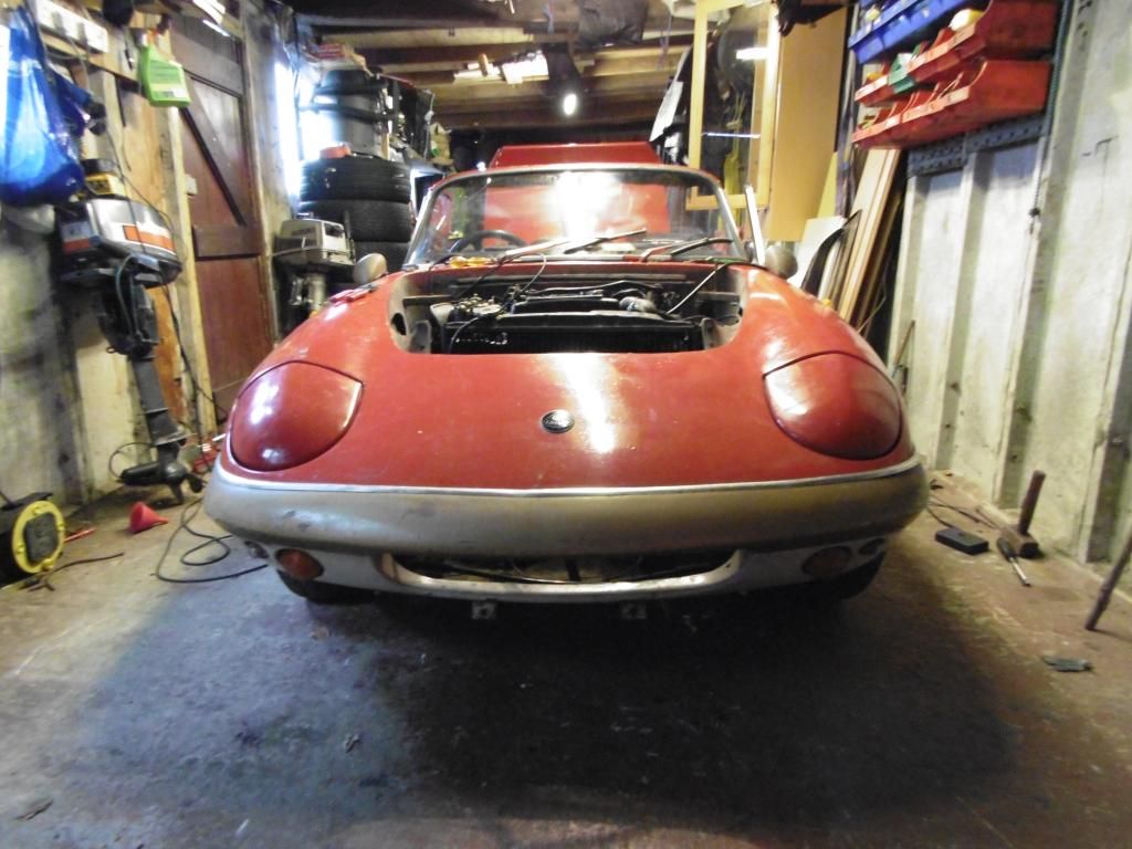
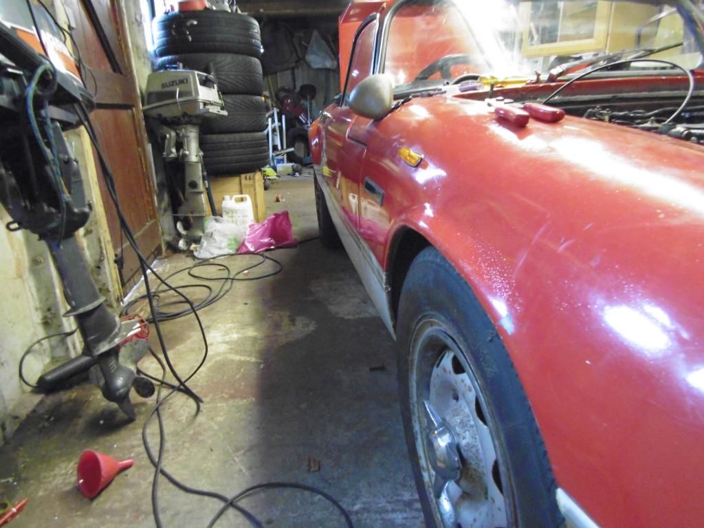
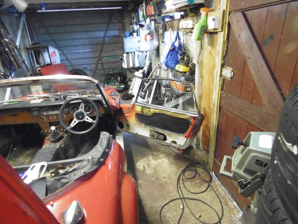
Ok lets start the story....... My parents moved House 34 years ago and this was the last journey the elan made under its own steam. It was parked up in the garage with a rotten chassis and the plaque of other problems p.s I wasn't even born yet so this is my dads turn of events. My mum wanted to sell it as interest rates rose and things were tight. So my dad took it to bits to avoid the inevitable.
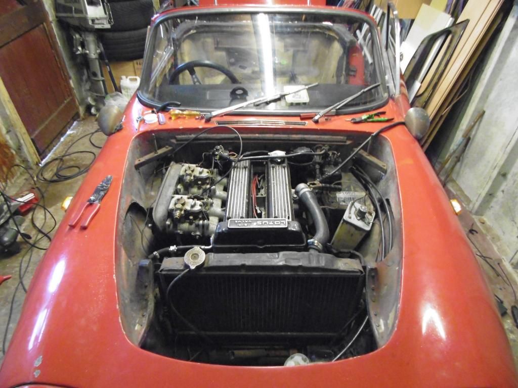
About 25 years ago my dad had a bash at the restoration, rebuilding the engine, buying another chassis and getting it rolling. For one reason or another it halted at this point.
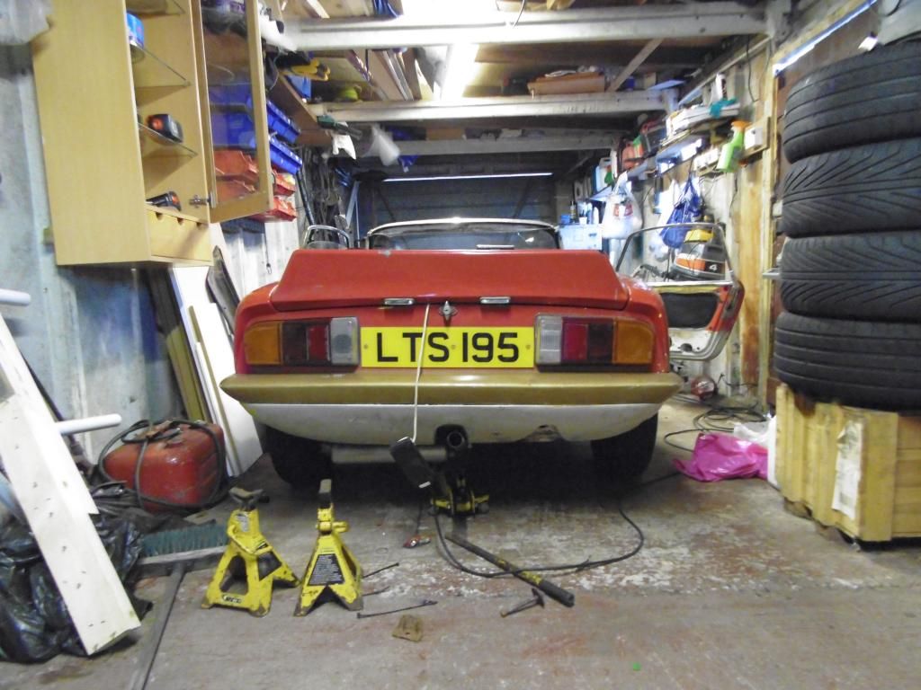
20 years ago I became a nagging teenager who wanted to take everything to pieces and attempt to rebuild them so I nagged the old man to start working on it. We got the engine in, got it running got the body shell positioned on and almost to a driving position, then things once again halted (I'm sure girls became more important that cars at that point in my life ) so it has sat in its current position for the last 14/15 years.
So now my dad is semi retired and we are starting to get things moving again so you will probably see me on here with the daftest of questions at time. P.S amazingly some fresh fuel and fresh battery and away she went.........
We are trying to complete this on a budget and get it road worthy and continually improve it from there. I am looking at a new fuel tank and sender unit (I should have said earlier that the S3 has morphed into a sprint at some point in its life) and the sender unit looks to be pretty god dam expensive for what it is.....After a little research it looks like the Austin mini van is very similar and less than half the ?, so does anyone know if this will fit?
Thanks,
Steven
About 25 years ago my dad had a bash at the restoration, rebuilding the engine, buying another chassis and getting it rolling. For one reason or another it halted at this point.
20 years ago I became a nagging teenager who wanted to take everything to pieces and attempt to rebuild them so I nagged the old man to start working on it. We got the engine in, got it running got the body shell positioned on and almost to a driving position, then things once again halted (I'm sure girls became more important that cars at that point in my life
So now my dad is semi retired and we are starting to get things moving again so you will probably see me on here with the daftest of questions at time. P.S amazingly some fresh fuel and fresh battery and away she went.........
We are trying to complete this on a budget and get it road worthy and continually improve it from there. I am looking at a new fuel tank and sender unit (I should have said earlier that the S3 has morphed into a sprint at some point in its life) and the sender unit looks to be pretty god dam expensive for what it is.....After a little research it looks like the Austin mini van is very similar and less than half the ?, so does anyone know if this will fit?
Thanks,
Steven
Last edited by s28ven on Sat Oct 04, 2014 6:54 pm, edited 1 time in total.
- s28ven
- Second Gear

- Posts: 67
- Joined: 30 Sep 2014
Hello Steven,
Welcome to the forum
There are plenty of knowledgeable and helpful people on the forum, I'm sure somebody will be able to tell you about the sender. Have you tried the forum search function? It's not great but you never know what it may turn up.
If you have a mo post some pictures.
All the best,
Rob
-

Mazzini - Coveted Fifth Gear

- Posts: 2046
- Joined: 11 Dec 2010
I dont know about the Mini sender but doubt it would work (or even be accurate).... but who knows 
As far as I am aware the S1/2/3 sender is no longer available, only the S4 type can still be purchased.
Unfortunately the S4 sender does not work with the S3 gauge as the sender has a different resistance and as I remember works the opposite way round i.e. full = empty.
Sometimes the sender can be repaired if the windings are not too badly damaged or I suppose both a S4 gauge and sender (and stabilizer) could be fitted.
Failing that there is always the graduated stick method
Brian
64 S2 Roadster
72 Sprint FHC
64 S2 Roadster
72 Sprint FHC
-

types26/36 - Coveted Fifth Gear

- Posts: 3406
- Joined: 11 Sep 2003
thanks for your replies guys.
I will hopefully get some pictures up over the weekend.
I have found a gasket image with dimensions which ties up with the original sender hole on the original tank so I will give it a bash and let you all know. Surely if the gauge was reading the wrong way you would just rotate it 180degrees??
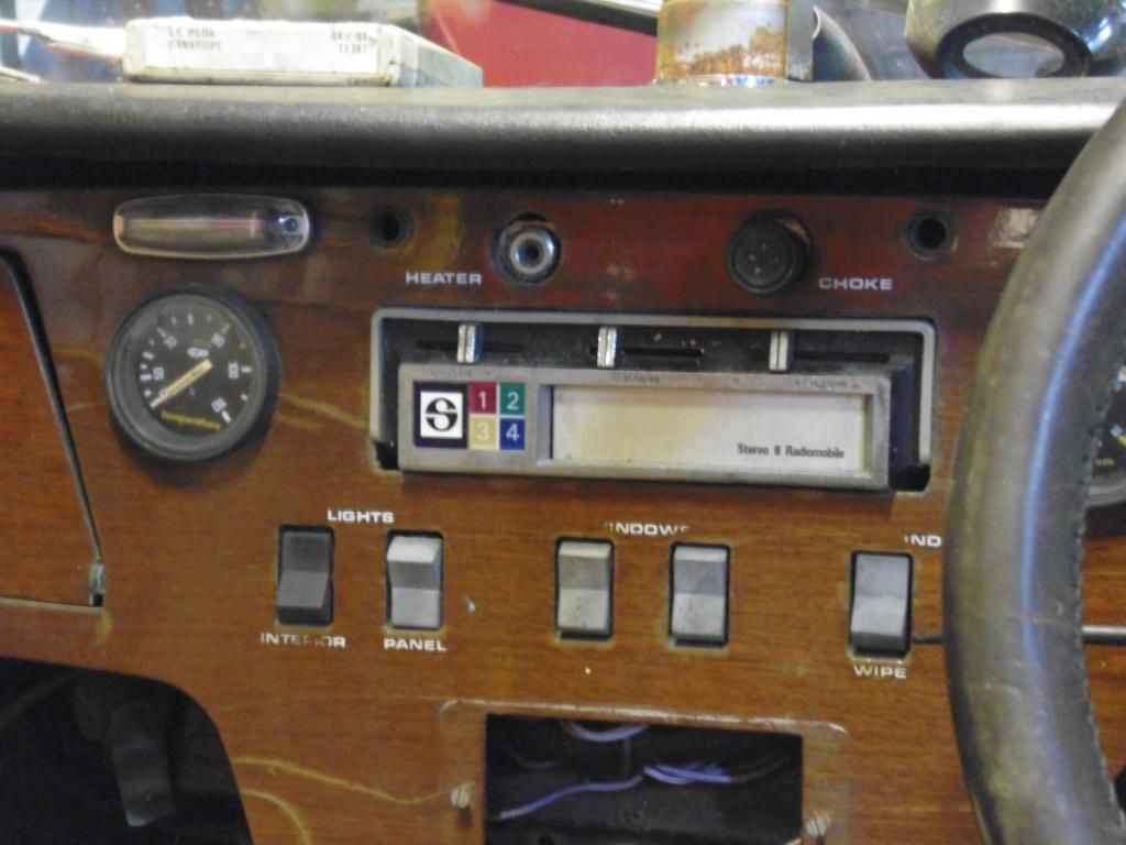
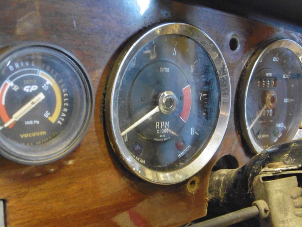
I'm honestly not totally clued up on the difference between the S3 & S4 gauges so cant really comment. I will get some pictures of the gauges as well.
We are currently awaiting the calliper's returning from Brakes international who were a good bit cheaper than usual suppliers although they never had any exchange units in stock so we had to send our old ones away. Hopefully be back early next week.
I've just ordered a tank and two rotoflex units and other bits from SJ so hopefully they don't take too long and we can get on a bit further
Thanks,
Steven
- s28ven
- Second Gear

- Posts: 67
- Joined: 30 Sep 2014
Hello Steven,
I think it may not be a matter of just inverting the sender as I think the resistance value is different also. If this is so, then the S3 and S4 guages will have different sensitivity
Eric in Burnley
1967 S3 SE DHC
I think it may not be a matter of just inverting the sender as I think the resistance value is different also. If this is so, then the S3 and S4 guages will have different sensitivity
Eric in Burnley
1967 S3 SE DHC
- ericbushby
- Coveted Fifth Gear

- Posts: 1368
- Joined: 13 Jun 2011
Hi Steven,
I have some notes on the resistances which I've no doubt collected either from this forum or the old Yahoo group forum with a final comment on the variability & undocumented changes that goes with these cars.
I did exactly the same thing that you're thinking of and bought a cheaper sender with the right fixing and resistance range and then bent the arm to suit the range of movement required. Sadly, I can't remember the car (MG ?) but the key thing was the resistance range they work on, the rest you can modify to get a workable result.
But before you do, have you stripped the old one down first and checked that it's really broken ? If the internal resistance wire has worn/snapped then I couldn't successfully make a long term repair, but if it's just dirt or the arm not connecting properly then you might be able to get it working ?
Brian
I have some notes on the resistances which I've no doubt collected either from this forum or the old Yahoo group forum with a final comment on the variability & undocumented changes that goes with these cars.
"S1, S2, and S3 models used mostly the 0 Empty to 90 ohms Full sending units. S4 and Sprint models also used the 6 ohms Empty to 77 ohms Full sending units
I also encountered a 253 ohms Empty to 25 ohms Full OEM sender and OEM S4 Elan fuel gauge in a friend's car in California. Sounds to me like Colin might have been using whatever was in the bin on occasion."
I did exactly the same thing that you're thinking of and bought a cheaper sender with the right fixing and resistance range and then bent the arm to suit the range of movement required. Sadly, I can't remember the car (MG ?) but the key thing was the resistance range they work on, the rest you can modify to get a workable result.
But before you do, have you stripped the old one down first and checked that it's really broken ? If the internal resistance wire has worn/snapped then I couldn't successfully make a long term repair, but if it's just dirt or the arm not connecting properly then you might be able to get it working ?
Brian
-

UAB807F - Fourth Gear

- Posts: 605
- Joined: 20 Dec 2010
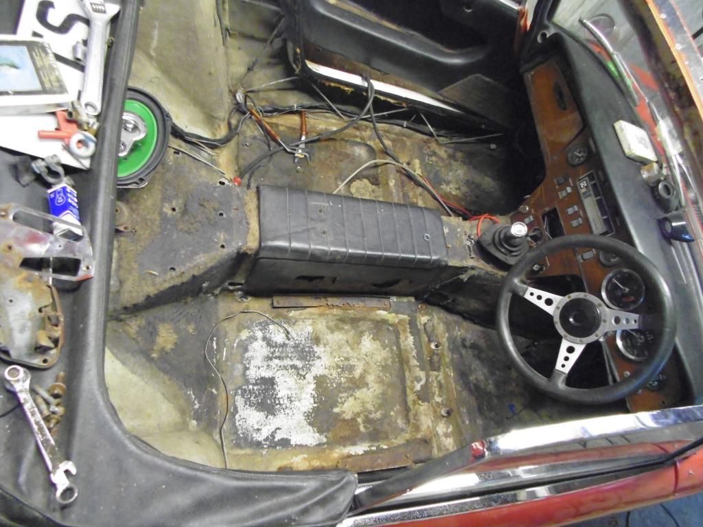
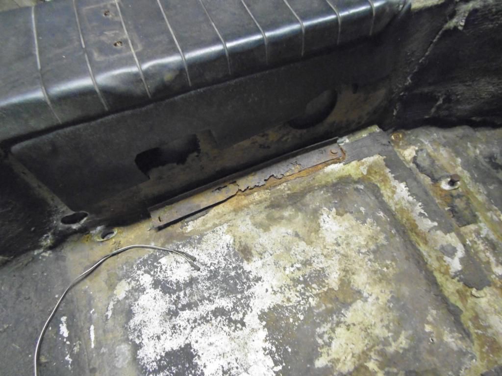
Ok guys here is another one of my silly questions, well hopefully..... The bolt holes in the body below the seat belt fixing point don't line up with the holes in the chassis. At this location there isn't any bobbins installed either but you can tell by looking through the oval hole in the body that if a bobbin was installed it wouldn't line up.
So my question is do I cut the existing bobbin holding points out and fix new bobbins in fiberglass in the correct/new location to suit the chassis or do I drill out the chassis?
Also I bought new plastic wheels for the electric window's, now are there different sizes of these as the existing ones are a lot smaller than the new ones and they seem to be very stiff on the existing spigot and if anything I expected these to be loose.
Thanks,
Steven
- s28ven
- Second Gear

- Posts: 67
- Joined: 30 Sep 2014
s28ven wrote:Ok guys here is another one of my silly questions, well hopefully..... The bolt holes in the body below the seat belt fixing point don't line up with the holes in the chassis. At this location there isn't any bobbins installed either but you can tell by looking through the oval hole in the body that if a bobbin was installed it wouldn't line up.
So my question is do I cut the existing bobbin holding points out and fix new bobbins in fiberglass in the correct/new location to suit the chassis or do I drill out the chassis?
Also I bought new plastic wheels for the electric window's, now are there different sizes of these as the existing ones are a lot smaller than the new ones and they seem to be very stiff on the existing spigot and if anything I expected these to be loose.
Thanks,
Steven
From what you say I understand you have no bobbin in the body where the bolt fits vertically up through the chassis to the body just below the seat belt mounting bolt, and you just have an oval hole. The oval hole does not line up with the hole in the chassis also.
It sounds like the bobbin has been previously cut out with the intention of fitting a new one that lines up with the hole in the chassis. You could continue down that route which would be my preference. The alternative is to fit a bobbin in the oval hole and redrill the chassis. Either should work provided the location of the bobbin does not interfere with the seat track and rear seat track bolt which is close to this location. The seat track bolt at the track rear goes through the body and chassis also so make sure you are not confusing this bolt hole for the body mount hole.
Cant help with the issue with the new window cable wheels and the size of the new ones you have got but they should spin freely while not being so loose that they tilt and the cables can slip off.
cheers
Rohan
-

rgh0 - Coveted Fifth Gear

- Posts: 8431
- Joined: 22 Sep 2003
Rohan, that's exactly right.
The bobbins I got from SJ sports cars have a flange on both sides so do I cot the bobbin in half and insert one half from the bottom and one from the top or do I need to cut and re fiberglass the new one in?
Thanks,
Steven
The bobbins I got from SJ sports cars have a flange on both sides so do I cot the bobbin in half and insert one half from the bottom and one from the top or do I need to cut and re fiberglass the new one in?
Thanks,
Steven
- s28ven
- Second Gear

- Posts: 67
- Joined: 30 Sep 2014
17 posts
• Page 1 of 2 • 1, 2
Total Online:
Users browsing this forum: No registered users and 31 guests

