
Oval rear control arms
![]() Post by: GrUmPyBoDgEr » Sun Dec 30, 2012 5:25 pm
Post by: GrUmPyBoDgEr » Sun Dec 30, 2012 5:25 pm
worzel wrote:Hi
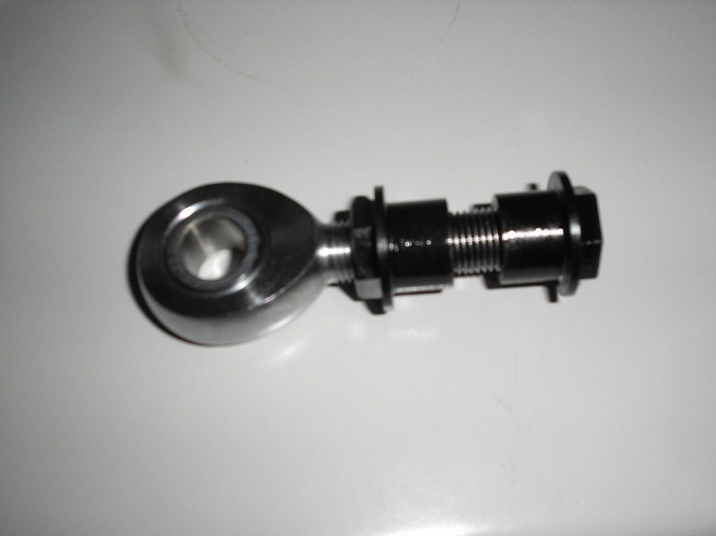
Some interesting comments on this issue. I wasn't too keen on the turnbuckle system so I had a pair of new frames made by TTR. They use the original bushes but adjust on the car- one on each frame uses a locknut only so the initial setting on this needs to be accurately done. The other bush is adjustable on the car- the threaded part runs thru an unthreaded tube and is locked via two locknuts, one either side of the mounting. I'll post a picture later to clarify things.
Regards
John
Now that idea I really do like, maybe some nyloc nuts could be used but probably overkill.
Best solution for adjusting alignment that I've seen to date
Editor: On Sunday morning, February 8th 2015, Derek "John" Pelly AKA GrumpyBodger passed away genuinely peacefully at Weston Hospicecare, Weston Super Mare. He will be missed.
-

GrUmPyBoDgEr - Coveted Fifth Gear

- Posts: 3062
- Joined: 29 Oct 2004

![]() Post by: stevebroad » Sun Dec 30, 2012 5:28 pm
Post by: stevebroad » Sun Dec 30, 2012 5:28 pm
- stevebroad
- Fourth Gear

- Posts: 917
- Joined: 08 Mar 2004
![]() Post by: stevebroad » Sun Dec 30, 2012 5:36 pm
Post by: stevebroad » Sun Dec 30, 2012 5:36 pm
worzel wrote:Hi
Some interesting comments on this issue. I wasn't too keen on the turnbuckle system so I had a pair of new frames made by TTR. They use the original bushes but adjust on the car- one on each frame uses a locknut only so the initial setting on this needs to be accurately done. The other bush is adjustable on the car- the threaded part runs thru an unthreaded tube and is locked via two locknuts, one either side of the mounting. I'll post a picture later to clarify things.
Regards
John
I guess you mean something like this? I know it's the front but the idea is the same:
- stevebroad
- Fourth Gear
- Posts: 917
- Joined: 08 Mar 2004
![]() Post by: Quart Meg Miles » Sun Dec 30, 2012 5:43 pm
Post by: Quart Meg Miles » Sun Dec 30, 2012 5:43 pm
Regarding the earlier triangulation I agree with Grumps, there's insignificant change in lozenge strength. What twisting are you trying to reduce, just fore and aft hub movement (which I call lozenging)?
Back in the days of the Terrapin DIY race car, suspension designed by the "string computer", the BRM team advised the designer to add a triangulating strut to control side whip in a long trailing arm but I don't see anything in the Elan/+2 comparable.
If you do think that the shape is distorting then weld a sheet of steel to the whole frame.
26/4088 1965 S1½ Old and scruffy but in perfect working order; the car too.
________________Put your money where your mouse is, click on "Support LotusElan.net" below.
-

Quart Meg Miles - Coveted Fifth Gear
- Posts: 1278
- Joined: 03 Oct 2012

![]() Post by: stevebroad » Sun Dec 30, 2012 6:09 pm
Post by: stevebroad » Sun Dec 30, 2012 6:09 pm
Quart Meg Miles wrote:Steve, those control arms must have cost more than my car!
Regarding the earlier triangulation I agree with Grumps, there's insignificant change in lozenge strength. What twisting are you trying to reduce, just fore and aft hub movement (which I call lozenging)?
Back in the days of the Terrapin DIY race car, suspension designed by the "string computer", the BRM team advised the designer to add a triangulating strut to control side whip in a long trailing arm but I don't see anything in the Elan/+2 comparable.
If you do think that the shape is distorting then weld a sheet of steel to the whole frame.
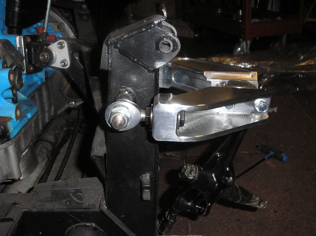
Not quite
Whilst adding the ARB brackets we discussed ways of reducing flex in the tubes. By triangulation we have at least dealt with movement in one plane quite well. Until we test the car under full power we won't know if anything else is required. We may have to have a rethink.
- stevebroad
- Fourth Gear
- Posts: 917
- Joined: 08 Mar 2004
![]() Post by: JJDraper » Sun Dec 30, 2012 6:15 pm
Post by: JJDraper » Sun Dec 30, 2012 6:15 pm
Those alloy arms are gor-ge-ous!
With regards to stresses on the 'A' frames, has anyone had one fail? I have seen plenty of bent ones, but never a broken one. I had oval section frames, which suffered the usual 'jack up' damage (over enthusiatic MOT tester), which dented the tube slightly, but didn't bend it. This suggests they are stiffer and more resistant to damage/flex. I did however bend one on my +2 after a clout with a curb (don't ask, I blame mud on the road) which also cracked the alloy wheel and bent the outer drive shaft. The turnbuckle solution is one solution and allows reasonably rapid adjustment. The rose joint solution looks like you have to disassemble the arm (both bolts or you will twist the arm) and turn the rod end, bolt it all up; measure toe in and disassemble again if further adjustment required repeat until the toe in is correct.. The front wishbone solution (not the alloy one) seems to suffer from the same 'measure; take it all apart; half turn; bolt all back up; measure & repeat as necessary' problem. This may be OK for race car, but a road car? We've been down this route before when I suggested that the wheel bearings could be adjusted using shims to get the exact free play!
If we are going down the hang the expense route, has anyone tried variable rate springs? With a lightweight car, I would have thought this was a reasonable suggestion, but I haven't seen any yet...
Jeremy
-

JJDraper - Coveted Fifth Gear
- Posts: 1031
- Joined: 17 Oct 2004

![]() Post by: stevebroad » Sun Dec 30, 2012 6:54 pm
Post by: stevebroad » Sun Dec 30, 2012 6:54 pm
JJDraper wrote:
Those alloy arms are gor-ge-ous!
The rose joint solution looks like you have to disassemble the arm (both bolts or you will twist the arm) and turn the rod end, bolt it all up; measure toe in and disassemble again if further adjustment required repeat until the toe in is correct.
Jeremy
Thank you. If you would like a set............
With regard to the rear wishbone rod end, it turns within the chassis mounting tags so no dismantling required, just the removal of the rod end securing bolt.
- stevebroad
- Fourth Gear
- Posts: 917
- Joined: 08 Mar 2004
![]() Post by: Elanman99 » Sun Dec 30, 2012 9:50 pm
Post by: Elanman99 » Sun Dec 30, 2012 9:50 pm
If the purpose of the extra welded in tubes was to add stiffness to the flat plane of the wishbone for the sake of the anti roll bar mount, then surely another corner to corner diagonal (creating an 'X' shape) would have been a significantly better method?
I'm curious too about the 'obvious shortcomings of the original design with regard to twisting' How does this manifest itself in practice?
Ian
-

Elanman99 - Fourth Gear
- Posts: 729
- Joined: 11 Sep 2003

![]() Post by: garyeanderson » Sun Dec 30, 2012 10:24 pm
Post by: garyeanderson » Sun Dec 30, 2012 10:24 pm
Harvey wrote:Ten years ago I purchased a +2 Spyder chassis and Spyder non-adjustable rear control arms. The arms' tubes were oval and not round like my original control arms.
I just had my rear toe measured by a laser alignment machine at the local tire shop. On the left side I had .08" of toe-out and on the right had .01" of toe-in. I want to change the left side toe-out to toe-in and increase the amount of toe-in on the right. I am aware that Spyder and Kelvedon now make adjustable rear control arms that extend the rear tube via a turnbuckle to permit toe adjustment. I am also aware of an extensive past discusssion on this site titled, "adjustable rear control arms" wherein several clever Lotus owners have fabricated tube inserts and threaded rods to do what Spyder and Kelvedon have done, perhaps better.
My question for the forum is whether anyone has modified rear control arm tubes that are oval rather than round? If so, how did you get the round tubular inserts to match up with the oval tubes?
Lee
This may be a little late but did the rear arms have new bushes in the inners before the alignment was checked? The bushes can take an off center set after years of static weight bearing on them. most of it will be in the same direction as the weight. I pulled this bush out of one of the rear A frames this summer and I am not sure I posted the photo, It may be worth looking at before you cut up those Spyder arms, I used to have a pair but they left my hands when I sold 45/8221.
 Viewed 944 times")
-

garyeanderson - Coveted Fifth Gear
- Posts: 3391
- Joined: 12 Sep 2003

![]() Post by: bast0n » Sun Dec 30, 2012 10:26 pm
Post by: bast0n » Sun Dec 30, 2012 10:26 pm
I'm curious too about the 'obvious shortcomings of the original design with regard to twisting' How does this manifest itself in practice?
For ordinary mortals it doesn't...................................
- bast0n
- Third Gear

- Posts: 312
- Joined: 31 Oct 2008
![]() Post by: rgh0 » Sun Dec 30, 2012 10:35 pm
Post by: rgh0 » Sun Dec 30, 2012 10:35 pm
JJDraper wrote:With regards to stresses on the 'A' frames, has anyone had one fail? I have seen plenty of bent ones, but never a broken one.
If we are going down the hang the expense route, has anyone tried variable rate springs? With a lightweight car, I would have thought this was a reasonable suggestion, but I haven't seen any yet...
Jeremy
I have broken an A frame on my Elan. It failed just outboard of the rear inner pivot next to where the inner longitudinal tube joins. made for interesting handling when it let go, i now keep a close eye for cracks in this area. I think the failure was due to the loads flexiing the tube at this point under racing conditions.
The Elan effectively has a variable rate rear suspension with the rubber Aeon springs coming into play relatively early in the suspension travel and then providing a rising spring rate as they compress. Spacing these Aeon springs down to bring them into play earlier can greately improve the handing on the limit
cheers
Rohan
-

rgh0 - Coveted Fifth Gear
- Posts: 8829
- Joined: 22 Sep 2003

![]() Post by: Quart Meg Miles » Sun Dec 30, 2012 11:33 pm
Post by: Quart Meg Miles » Sun Dec 30, 2012 11:33 pm
Which static weight is that, Gary, only the outer front bush carries any weight. There is a slight outward pull resolving the angle of the rear spring's ~350 lb at an angle of 75? which amounts to ~90 lb (and the inner front is about the same). Do you think 90 lb is enough to distort the bush over time?piss-ant wrote:This may be a little late but did the rear arms have new bushes in the inners before the alignment was checked? The bushes can take an off center set after years of static weight bearing on them. most of it will be in the same direction as the weight.
26/4088 1965 S1½ Old and scruffy but in perfect working order; the car too.
________________Put your money where your mouse is, click on "Support LotusElan.net" below.
-
Quart Meg Miles - Coveted Fifth Gear
- Posts: 1278
- Joined: 03 Oct 2012
![]() Post by: garyeanderson » Sun Dec 30, 2012 11:55 pm
Post by: garyeanderson » Sun Dec 30, 2012 11:55 pm
Quart Meg Miles wrote:Which static weight is that, Gary, only the outer front bush carries any weight. There is a slight outward pull resolving the angle of the rear spring's ~350 lb at an angle of 75? which amounts to ~90 lb (and the inner front is about the same). Do you think 90 lb is enough to distort the bush over time?piss-ant wrote:This may be a little late but did the rear arms have new bushes in the inners before the alignment was checked? The bushes can take an off center set after years of static weight bearing on them. most of it will be in the same direction as the weight.
I don't know what caused the bush to be like that. It was from 26/4997 and I guess that they are probably original. So they (more than one) were in the Elan from 1965 to 2012. my guess is they were not made like that but they may have been, I guess the bottom line is if you were carrying 90 lbs or what ever they had on them you may sag a bit too
Gary
-
garyeanderson - Coveted Fifth Gear
- Posts: 3391
- Joined: 12 Sep 2003
![]() Post by: stevebroad » Mon Dec 31, 2012 12:04 am
Post by: stevebroad » Mon Dec 31, 2012 12:04 am
Elanman99 wrote:That the weirdest 'A' frame I've ever seen!
If the purpose of the extra welded in tubes was to add stiffness to the flat plane of the wishbone for the sake of the anti roll bar mount, then surely another corner to corner diagonal (creating an 'X' shape) would have been a significantly better method?
I'm curious too about the 'obvious shortcomings of the original design with regard to twisting' How does this manifest itself in practice?
Ian
You may be right, but I did this (after a reasoned discussion) on the advice of my chassis guru, Graham Hatherway, who has been bulding race cars for many years. The worst that can happen is we are carrying a little extra weight. Once we run the car at full power and grip we will know the answer
- stevebroad
- Fourth Gear
- Posts: 917
- Joined: 08 Mar 2004
![]() Post by: Harvey » Mon Dec 31, 2012 12:19 am
Post by: Harvey » Mon Dec 31, 2012 12:19 am
I have not checked the bushings since the control arms were fitted to the Spyder chassis 10 years ago. Since then I have covered about 30,000 miles. I will look the bushings over carefully when I remove them from the car in about a week
Thanks,
Lee
- Harvey
- Second Gear

- Posts: 127
- Joined: 21 Aug 2010
Total Online:
Users browsing this forum: Elanman99 and 21 guests