
Oval rear control arms
51 posts
• Page 1 of 4 • 1, 2, 3, 4
![]() Post by: Harvey » Sat Dec 29, 2012 1:13 am
Post by: Harvey » Sat Dec 29, 2012 1:13 am
Ten years ago I purchased a +2 Spyder chassis and Spyder non-adjustable rear control arms. The arms' tubes were oval and not round like my original control arms.
I just had my rear toe measured by a laser alignment machine at the local tire shop. On the left side I had .08" of toe-out and on the right had .01" of toe-in. I want to change the left side toe-out to toe-in and increase the amount of toe-in on the right. I am aware that Spyder and Kelvedon now make adjustable rear control arms that extend the rear tube via a turnbuckle to permit toe adjustment. I am also aware of an extensive past discusssion on this site titled, "adjustable rear control arms" wherein several clever Lotus owners have fabricated tube inserts and threaded rods to do what Spyder and Kelvedon have done, perhaps better.
My question for the forum is whether anyone has modified rear control arm tubes that are oval rather than round? If so, how did you get the round tubular inserts to match up with the oval tubes?
Lee
Jackson, CA
- Harvey
- Second Gear

- Posts: 127
- Joined: 21 Aug 2010
![]() Post by: stevebroad » Sat Dec 29, 2012 3:50 pm
Post by: stevebroad » Sat Dec 29, 2012 3:50 pm
Who in their right mind would adjust to-in/out by stressing the joints on the A-frame? IMO, this is utter incompetance and bloody dangerous.
The simplest way, and it works on round and oval tubes, is shown below. The to-in/out can be adjusted insitu as the rod end will turn within the chassis mounting tabs. You will, however, have to make spacers to take up the difference in width between the original bush and the new rod end.
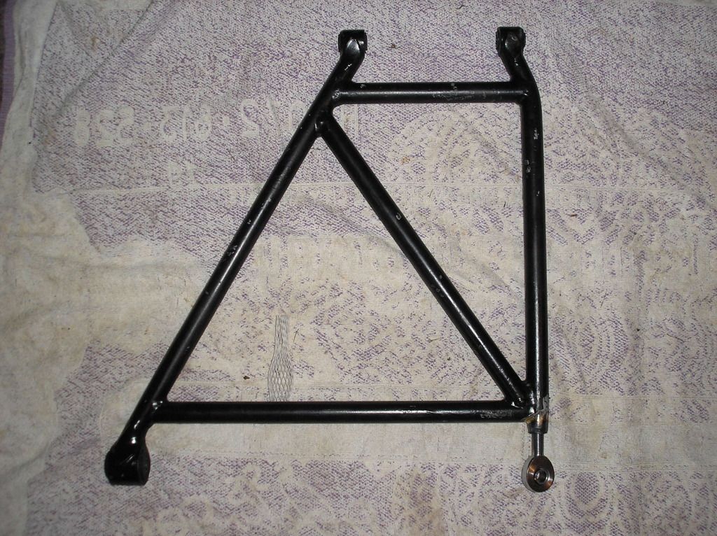
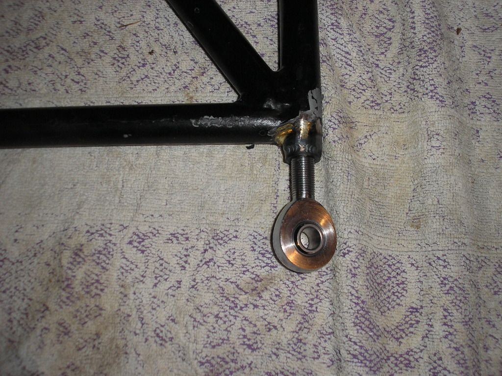
The simplest way, and it works on round and oval tubes, is shown below. The to-in/out can be adjusted insitu as the rod end will turn within the chassis mounting tabs. You will, however, have to make spacers to take up the difference in width between the original bush and the new rod end.
- stevebroad
- Fourth Gear

- Posts: 917
- Joined: 08 Mar 2004
![]() Post by: spanner » Sat Dec 29, 2012 6:32 pm
Post by: spanner » Sat Dec 29, 2012 6:32 pm
Harvey wrote:
My question for the forum is whether anyone has modified rear control arm tubes that are oval rather than round? If so, how did you get the round tubular inserts to match up with the oval tubes?
Lee
Hi Lee,
A special flanged barrel is used on aircraft streamline tubing for this purpose. The larger weld area greatly increases the strength. The open end can be tapered and welded.
http://univairparts.com/bulletin_direct ... 200120.pdf
https://www.aircraftspruce.com/pages/lg ... bsets3.php
http://www.ebay.com/itm/Piper-Style-5-8 ... 0592946916
Good luck with your project.
S-B
- spanner
- Second Gear
- Posts: 111
- Joined: 06 Mar 2008
![]() Post by: Harvey » Sat Dec 29, 2012 8:17 pm
Post by: Harvey » Sat Dec 29, 2012 8:17 pm
Steve,
Thank you for your response and the clear pictures of your modification to your control arms. The machinist/welder who is going to modify my arms also questioned the stresses placed on the arms by the turnbuckle expansion setup even though I told him that Spyder and Kelvedon have been selling this type of adjustable control arms for years seemingly without safety issues. The machinist is familiar with fabricating suspensions for formula cars and the use of rod ends to adjust rear toe. We discussed rod ends and he did not think they were the best choice for street cars and prefers to stay with the metalastic bushings. I wil, nevertheless, forward your response on to him.
S-B
The flanged inserts you have pointed me to look like they would mate up nicely to my oval arms with a bit of careful welding. I will pass this information on to my machinist. Thanks for the links to the inserts and to the instructions for attaching them to the arms.
Lee
Jackson, CA
- Harvey
- Second Gear
- Posts: 127
- Joined: 21 Aug 2010
![]() Post by: stevebroad » Sat Dec 29, 2012 11:57 pm
Post by: stevebroad » Sat Dec 29, 2012 11:57 pm
Just because they haven't had a problem doesn't make it a good idea. Would ACBC do it? I don't think so.
You can do the same with a metalastic bush, as shown below:
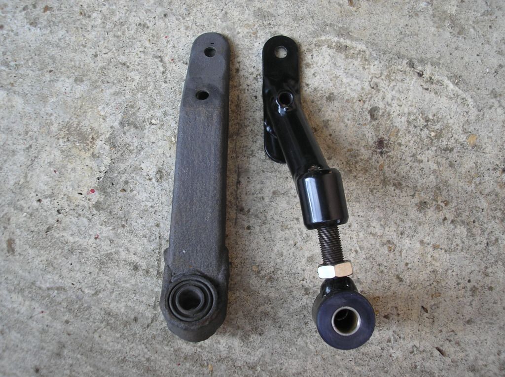
However, you will have to remove both chassis bolts and drop the arm to adjust as it won't turn in the chassis mount.
With 3 bushes remaining I don't think one rod end will make a noticable difference to the noise or feel.
You can do the same with a metalastic bush, as shown below:
However, you will have to remove both chassis bolts and drop the arm to adjust as it won't turn in the chassis mount.
With 3 bushes remaining I don't think one rod end will make a noticable difference to the noise or feel.
- stevebroad
- Fourth Gear
- Posts: 917
- Joined: 08 Mar 2004
![]() Post by: ceejay » Sun Dec 30, 2012 3:14 am
Post by: ceejay » Sun Dec 30, 2012 3:14 am
The adjustment of the rear A arms via the left hand - right hand
threaded adjusters is acceptable engineering practice. The thing that
most people over look is the small amount of + or - movement required
to achieve correct toe settings, on the adjuster it amounts to as little as
three quarters of one turn.... in other words, the A frame hardly moves,
and is certainly not subject to excessive stress or strain.
If the A arm requires a large amount of movement to obtain correct toe
settings it was probably badly made in the first place, or it has suffered
a decent whack in it's past life.
But it does not matter how expensive or accurate the jigging system being
used is during A arm fabrication, the A arm will pull or move slightly, it is a
natural thing with metal, during and after being welded.
Whether new A arms are bang constructed, or an old pair is being modified,
there is a lot of careful fabricating work involved, but the results speak for
themselves when the final laser alignment is completed.
The metal used to construct A arms is nothing more than 7/8" OD mild steel ERW
tube, sure, if one wants something a bit more exotic, build them from DOM tube,
or choose 4140 Crmoly, but then, it is quite expensive to buy, and more
difficult to weld and TIG is the only way to go.
But with ERW mild steel tube, nickel bronze weld is all that is required.
I wont get into the jigging and the fabricating set up, as that is a story
in itself.
Ceejay.
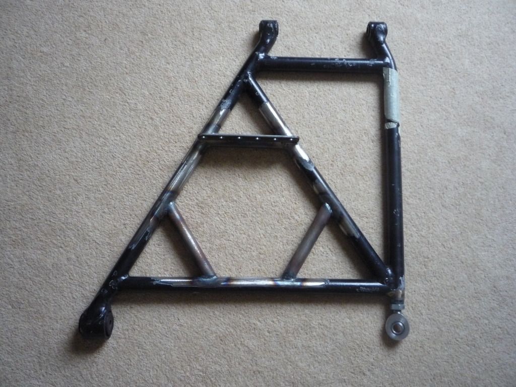
- Attachments
-

- If you have metal fabrication skills, it is not that difficult to build a set of rear A arms.
-

- This is what the left - right threaded adjuster parts consist of.
-

- Left - Right threaded weld in adjusters are an acceptable method of tweaking the A arms to obtain correct toe settings.
-

- The laser aligner shows + 5mm toe out,which is far to much.
-

- Laser aligner after slight adjustment shows 1mm toe out, which is correct.


- ceejay
- Fourth Gear
- Posts: 623
- Joined: 27 Mar 2007
![]() Post by: stevebroad » Sun Dec 30, 2012 8:48 am
Post by: stevebroad » Sun Dec 30, 2012 8:48 am
If you are happy to add additional stresses to an already stressed component, then go ahead. It looks neat and adjustment is easier as there is no dismantling required. However, the race car builders I have spoken to consider this method to be bad engineering by people who don't really appreciate the stresses involved, so I took their advice and did it properly  (lMO)
(lMO)
- stevebroad
- Fourth Gear
- Posts: 917
- Joined: 08 Mar 2004
![]() Post by: ceejay » Sun Dec 30, 2012 9:59 am
Post by: ceejay » Sun Dec 30, 2012 9:59 am
One could argue the pros & cons on this till the cows come home.
If you are happy with a rattling rose joint A frame adjuster on a
road car, that's fine.
It's horses for courses... normal road driving does not
stress components like the stresses that are generated under
race conditions.
Even with this A frame adjustment mod, the A frames wont break,
you would be surprised at just how strong they really are.
- ceejay
- Fourth Gear
- Posts: 623
- Joined: 27 Mar 2007
![]() Post by: miked » Sun Dec 30, 2012 11:22 am
Post by: miked » Sun Dec 30, 2012 11:22 am
As a point of interest Steve, have you ever put a hacksaw through one of the rear tube? I have and they generally spring apart leaving a gap larger than the hacksaw blade. I know jack about metals and stress but would say that they are already stressed by the original build with the heat treatment that they receive. I ran an S4 for a number of years with the turnbuckle adjusters. I also run a Plus 2 with a set of these. The tweak from what would be considered normal is very tiny to give correct Toe in. It is only done once. I will be having a check for cracking at the front tube joints.
Where would you be considering the stress point? the front outside joints since most corrections are to toe in after the frames give toe out? I am only asking so don't take this the wrong way? Project/track S4 in build has rose jointed TTR frames.
Ceejay, Re: 1 mm toe out. Correct toe is "in" is it not, not toe out? Thus allowing flex to straight. I usually set about 1.5 mm per side giving 3 mm overall (road use).
Mike
Mike
Elan S4 Zetec
Suzuki Hustler T250
Suzuki TC120R trailcat
Yamaha YR5
Suzuki Vstrom 650XT
Suzuki TS185K
Elan S4 Zetec
Suzuki Hustler T250
Suzuki TC120R trailcat
Yamaha YR5
Suzuki Vstrom 650XT
Suzuki TS185K
-

miked - Coveted Fifth Gear

- Posts: 1233
- Joined: 29 Sep 2003

![]() Post by: worzel » Sun Dec 30, 2012 11:50 am
Post by: worzel » Sun Dec 30, 2012 11:50 am
Hi
Some interesting comments on this issue. I wasn't too keen on the turnbuckle system so I had a pair of new frames made by TTR. They use the original bushes but adjust on the car- one on each frame uses a locknut only so the initial setting on this needs to be accurately done. The other bush is adjustable on the car- the threaded part runs thru an unthreaded tube and is locked via two locknuts, one either side of the mounting. I'll post a picture later to clarify things.
Regards
John
- worzel
- Fourth Gear
- Posts: 626
- Joined: 13 Jan 2004
![]() Post by: stevebroad » Sun Dec 30, 2012 11:53 am
Post by: stevebroad » Sun Dec 30, 2012 11:53 am
miked wrote:As a point of interest Steve, have you ever put a hacksaw through one of the rear tube? I have and they generally spring apart leaving a gap larger than the hacksaw blade. I know jack about metals and stress but would say that they are already stressed by the original build with the heat treatment that they receive. I ran an S4 for a number of years with the turnbuckle adjusters. I also run a Plus 2 with a set of these. The tweak from what would be considered normal is very tiny to give correct Toe in. It is only done once. I will be having a check for cracking at the front tube joints.
Where would you be considering the stress point? the front outside joints since most corrections are to toe in after the frames give toe out? I am only asking so don't take this the wrong way? Project/track S4 in build has rose jointed TTR frames.
Ceejay, Re: 1 mm toe out. Correct toe is "in" is it not, not toe out? Thus allowing flex to straight. I usually set about 1.5 mm per side giving 3 mm overall (road use).
Mike
Hi Mike
A valid point. If buy cutting the tube you release any stored stresses, putting an adjuster in the cut bar would not add any additional stress to what was there originally. I therefore retract my previously stated strong views against the system. However I still, personally, prefer the rod end solution as the A-frame bars stay as one piece.
Due to the obvious shortcomings of the original design with regard to twisting we have attempted to strengthen our frames. Any thoughts on whether we will be successful?
- stevebroad
- Fourth Gear
- Posts: 917
- Joined: 08 Mar 2004
![]() Post by: TurbineHeli » Sun Dec 30, 2012 2:04 pm
Post by: TurbineHeli » Sun Dec 30, 2012 2:04 pm
Hi Steve, what is the purpose of the plate with 6 holes?
Thanks,
AMA
Thanks,
AMA
- TurbineHeli
- Second Gear
- Posts: 64
- Joined: 24 Nov 2012
![]() Post by: stevebroad » Sun Dec 30, 2012 2:08 pm
Post by: stevebroad » Sun Dec 30, 2012 2:08 pm
Anti-roll bar (or sway bar on your side of the pond).
- stevebroad
- Fourth Gear
- Posts: 917
- Joined: 08 Mar 2004
![]() Post by: GrUmPyBoDgEr » Sun Dec 30, 2012 3:14 pm
Post by: GrUmPyBoDgEr » Sun Dec 30, 2012 3:14 pm
Sorry Steve but all I can see is a load of extra "un-triangulated" triangles adding no further stiffness as such.
Anyway the purpose is location & I don't recall any earlier discussion on the lack of stiffness in those frames.
Spyder claim improved stiffness with their ovalised tubing but don't explain what that brings with it.
Cheers
John
Anyway the purpose is location & I don't recall any earlier discussion on the lack of stiffness in those frames.
Spyder claim improved stiffness with their ovalised tubing but don't explain what that brings with it.
Cheers
John
Beware of the Illuminati
Editor: On Sunday morning, February 8th 2015, Derek "John" Pelly AKA GrumpyBodger passed away genuinely peacefully at Weston Hospicecare, Weston Super Mare. He will be missed.
Editor: On Sunday morning, February 8th 2015, Derek "John" Pelly AKA GrumpyBodger passed away genuinely peacefully at Weston Hospicecare, Weston Super Mare. He will be missed.
-

GrUmPyBoDgEr - Coveted Fifth Gear
- Posts: 3062
- Joined: 29 Oct 2004

51 posts
• Page 1 of 4 • 1, 2, 3, 4
Total Online:
Users browsing this forum: No registered users and 26 guests