Update: Clay test and Measuring Valve MOP
26 posts
• Page 1 of 2 • 1, 2
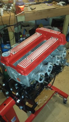
Since my last post, Ive managed to (hopefully) overcome the woes of a wonky timing cover. I seem to have achieved a reasonable seal all the way around the backplate, after much swearing and judicious use of silicone (I was ever cautious of the camchain oil jet).
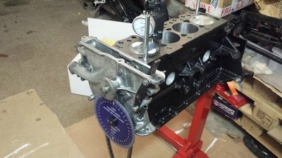
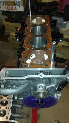
Since the head has been skimmed many times before, the machine shop expressed some concern that I might need an oversized head gasket to maintain adequate separation between the pistons and the valves. I decided to do a clay test in the spirit of other posts on this forum, to see for myself.
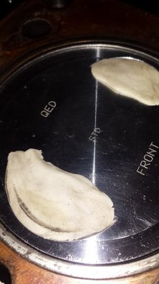
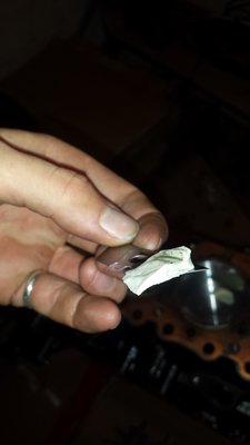
After filling the valve pockets with modelling clay, I built the head back with the old headgasket, which i believe to be a standard thickness. Much faffing later, I managed to jimmy the cam sprockets back into position, with the timing marks more or less where they should be. After a couple of full rotations, and without any binding (thankfully), I removed the head and found that only the intake valves had made an impression on the clay (as per photo). Using a sharp knife, I chopped the clay in half, and found a clearance of about 150thou. This seems plenty (I recall 60thou as a minimum), so this is good news i guess?
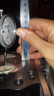
I'd like to make sure the engine is timed correctly. I know this is a well covered topic but I did have a quick question for the wise among us. Using a dial gauge, I've accurately determined where TDC is. But how do I use the dial guage to measure the point of maximum valve lift? There doesnt seem to be much space between the cam lobe and shim to poke it in there... Any help much appeciated .
This engine, despite its pitfalls and money draining abilities, is proving to be a great learning experience for an amature such as myself!!!
Best
Dave
- dlb123
- First Gear

- Posts: 48
- Joined: 19 Jan 2017
dlb123 wrote: But how do I use the dial guage to measure the point of maximum valve lift? There doesnt seem to be much space between the cam lobe and shim to poke it in there... Any help much appeciated .
Dave
Hi Dave,
Glad to hear your clay test worked fine !
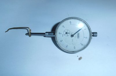
I measure valve lift with a small bit of suitably bent wire attached to the dial gauge thimble to measure off the bucket face, if that's what you mean
68 Elan +2, 70 Elan +2s
-

Foxie - Coveted Fifth Gear

- Posts: 1631
- Joined: 20 Sep 2003
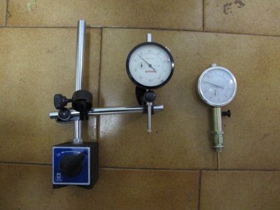
It's easy to measure the cam lift if you have a dial gauge mounted on a magnetic base. In my case there was enough room to get the dial gauge in to touch the bucket without having to add a pointer extension. Clip the magnetic base to the back of the block and observe the lift on number 4 cylinder inlet and exhaust valves. It takes a bit of manipulation of the magnetic base rods and arms but you can get the dial gauge in there. For setting the cam timing we aren't really interested in the absolute figure for lift (so there's no need to get the dial gauge measuring rod perfectly perpendicular to the bucket surface but the more perpendicular you can get it the more sensitive the measurement will be). Watch the gauge whilst turning the engine clockwise. Go very slowly as you reach peak lift. When the dial gauge pointer stops moving record the reading on the timing disc. Continue rotating clockwise very slowly. When the dial gauge pointer starts moving again record the reading on the timing disc. Your timing figure at maximum lift is then (first reading + second reading) / 2. I fitted vernier pulleys to my engine and they made the process of timing adjustment very easy. I preferred them to the thought of having to tap out or otherwise somehow extract tightly fitting dowel pins!
You mentioned your concern about valve to piston clearance. If you're running standard cams and pocketed pistons it should not be an issue even with a shaved head. I'd be more concerned about compression ratio if the the head's been skimmed a few times. Have you measured your combustion chamber and piston volumes to work out compression ratio? I found with my engine using QED pistons like yours and with a head previously skimmed a few times before that the compression ratio would have been too high had I used a standard copper gasket. Using a thicker composite gasket about 1.0mm thick however brought the compression ratio back to a reasonable 10.5:1 for road use. I'd suggest taking some measurements and doing some calculations.
Why did you use silicone around the front cover? That stuff is a PITA. It doesn't work well as a gasket dressing either. Use a dedicated gasket dressing compound such as the Aviation stuff mentioned by Rohan. Silicone is best used for a Formed In Place gasket and not as a gasket dressing.
1970 Ford Escort Twin Cam
1972 Ford Escort GT1600 Twin Cam
1980 Ford Escort 2.0 Ghia
Peugeot 505 GTI Wagons (5spdx1) (Autox1)
2022 Ford Fiesta ST.
1972 Ford Escort GT1600 Twin Cam
1980 Ford Escort 2.0 Ghia
Peugeot 505 GTI Wagons (5spdx1) (Autox1)
2022 Ford Fiesta ST.
- 2cams70
- Coveted Fifth Gear

- Posts: 2050
- Joined: 10 Jun 2015
Hi Dave
You are probably OK with a standard head gasket for normal road use assuming the head has not been machined down so that the lettering on the bottom face has gone ! Have you measured the thickness?
I measure the combustion chamber size by inverting the head with the valves and plugs in place and filling the chamber with liquid from a pipette,. Standard unmachined head ( 4.64 inch thick) chamber size is around 41cc The Sprint engine heads are around 37cc to 38 cc. (at 4.60 inch thick). The design of the valve heads ( e.g. flat versus dished andh ow thick ) and where valves are positioned in the head can significantly change these volumes.
cheers
Rohan
-

rgh0 - Coveted Fifth Gear

- Posts: 8829
- Joined: 22 Sep 2003
Hi Rohan,
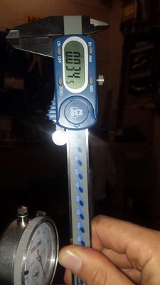
The head has had a significant amount taken off it. Now at 4.582" from a quick measure on the digital callipers. Such that the edge of the intake valves are just proud of the face. However the lettering has not been touched by the machining process, as you say.
Any thoughts?
Cheers.
Dave
The head has had a significant amount taken off it. Now at 4.582" from a quick measure on the digital callipers. Such that the edge of the intake valves are just proud of the face. However the lettering has not been touched by the machining process, as you say.
Any thoughts?
Cheers.
Dave
- dlb123
- First Gear

- Posts: 48
- Joined: 19 Jan 2017
4.582 should be fine still with a standard gasket and your comp ratio should be around 10.5 to 10.7 depending on other details which is fine with premium unleaded fuel.
Your valves sound like they are sitting a little to far away from the camshafts as I would expect standard big valve inlets in the right location to be inside the head face and not proud with a 4.58 thick head.
What is the overall valve length and head diameter and what is the distance from valve face to camshaft centre line. If you dont know that number (and most people dont) then you need to work it out from the following measurements.
cam base circle
valve clearance
bucket thickness
shim thickness
valve overall length
cheers
Rohan
-

rgh0 - Coveted Fifth Gear

- Posts: 8829
- Joined: 22 Sep 2003
According to my head test report thickness (pre machining) was 4.595" rear, 4.582" front (i.e 0.013" difference front to rear!) I expect it's now about the same thickness as yours at about 4.580" (except more even front to rear!) It has new seats and big valve spec. valves fitted. The inlet valve sits about 1mm proud of the head surface.
I would expect that due to the similar specification - head thickness and piston type, that your engine would be in a similar situation to mine compression ratio wise. The only difference is that your engine is running standard bore whereas mine's 0.060" oversize. Also my engine has close to zero piston to deck clearance.
I needed a thicker head head gasket than standard but you may just get away with a standard one due to running standard bore and (probably) standard deck clearance. You won't know for sure unless you measure it though.
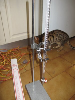
I used a 50mm burette filled with medicinal grade paraffin (available from chemists). To measure the head combustion chamber capacity you fit the spark plugs and cover the chamber with a piece of perspex with hole drilled to allow entry of the paraffin. You also need to determine the piston cut out volumes and measure the deck height. It's not a difficult procedure. I suggest you do some googling and come back with any questions you may have about it should you decide to do it. There's a bit a simple maths to do to work out the piston cutout volumes. Some people use kerosene and other liquids to fill the burette but medicinal paraffin works really well. It's clean, non toxic and importantly wont dissolve the vaseline seal between the perspex and head and also the top of the piston and bore whilst measuring.
Back to another issue - re. the clearance between backplate and block. Did you check the oil gallery plug for adequate clearance to the backplate? Rohan just posted about it in the thread about his build and I also posted about it several months ago as it affected my build too.
1970 Ford Escort Twin Cam
1972 Ford Escort GT1600 Twin Cam
1980 Ford Escort 2.0 Ghia
Peugeot 505 GTI Wagons (5spdx1) (Autox1)
2022 Ford Fiesta ST.
1972 Ford Escort GT1600 Twin Cam
1980 Ford Escort 2.0 Ghia
Peugeot 505 GTI Wagons (5spdx1) (Autox1)
2022 Ford Fiesta ST.
- 2cams70
- Coveted Fifth Gear

- Posts: 2050
- Joined: 10 Jun 2015
I use "Playdo" or what we used to call pasticine to measure the clearance in the same way as dlb123 did but, after I remove it from the (oiled) piston crown I put it in the freezer for an hour before cutting and measuring it. I find the very graphic evidence is calming...
'65 S2 4844
- Davidb
- Fourth Gear

- Posts: 942
- Joined: 02 Jul 2009
Another method of measuring the cylinder volume which may be simpler for you is to fit the head with gasket on temporarily and fill a cylinder with a burette through the spark plug hole. You will need to seal around the edges of the piston with Vaseline and ensure both valves are closed of course. Measure the volume at TDC and BDC and then it's a simple matter to work out compression ratio. You'd need to be careful with the filling to ensure that you don't get any bubbles because you can't see them using this method as you can through the Perspex with the other method.
1970 Ford Escort Twin Cam
1972 Ford Escort GT1600 Twin Cam
1980 Ford Escort 2.0 Ghia
Peugeot 505 GTI Wagons (5spdx1) (Autox1)
2022 Ford Fiesta ST.
1972 Ford Escort GT1600 Twin Cam
1980 Ford Escort 2.0 Ghia
Peugeot 505 GTI Wagons (5spdx1) (Autox1)
2022 Ford Fiesta ST.
- 2cams70
- Coveted Fifth Gear

- Posts: 2050
- Joined: 10 Jun 2015
Hi there.
Thanks for all the useful input guys. Ive made a few more strides with the engine.
I used the perspex method to measure the combustion chamber volume. I also used medicinal parrafin (thanks for the tip) which seemed to work very well, and was easy to clean up.
By my reckoning, the combustion chamber was just shy of 35cc. Does that sound about right, given the head thickness? Should
So, with that in mind I went and measured the gap between the deck and the top of the pistons. I came out with figure of between 3-3.5 thou. Bearing in mind this is a brand new block and new pistons. Does this seem a little on the tight side? Further more, the piston has a 'intrusion section', with a lower ring around the edge of the face (photo explains better). Where should I be measuring from? The recess around the edge, or the raised part. If it is tight I assume a thicker gasket may solve my woes...
I still need to dertermine the piston cutout volume and then work out the cylinder volumes... alas.
Rohan, in answer to your question about the intake valves sitting proud of the face. Originally, the intakes were very high in the head, and the shims were almost down to minium thickness. So the machine shop re-seated the valves. I admit, they probably could be sat a little higher than they are currently, but should I expect any issues? I'm not particularly keen on sending the head back in again.
Finally, 2cams70, I had the same issue with the bore plug interfering with the backplate to block fitment. I ended up having to remove a little material from the plate to get it to fit correctly. Nothing is easy with this build, though I'm chalking some of it up to inexperience.
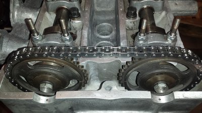
One more daft question. The machine shop polished the cams, and removed the sprockets in the process. When I got them back, the sprockets had been re-fitted incorrectly so I swapped them back. Humour me and have a look at this photo. TDC for piston 1 with the cam lobes pointing outwards. That right??
Thanks as always,
Dave
- dlb123
- First Gear

- Posts: 48
- Joined: 19 Jan 2017
Well it matches my picture 
.JPG)
Assuming you have not got the exhaust cam in the inlet cam position and the inlet sprocket is on the inlet cam and the outlet sprocket is on the outlet cam and since your two timing marks on the sprockets face each other you must have it correct.
The exhaust/outlet sprocket usually has the letters EX engraved on it. On your photo I can see IN scratched on the sprocket on the inlet side so that is correct. I cannot see EX scratched/engraved on the other sprocket.
Oddly enough I do not know how to distinguish the inlet cam from the outlet/exhaust cam; someone else will have to describe that.
Bill Williams
36/6725 S3 Coupe OGU108E Yellow over Black.
36/6725 S3 Coupe OGU108E Yellow over Black.
- billwill
- Coveted Fifth Gear

- Posts: 5062
- Joined: 19 Apr 2008
The inlet and exhaust camshafts should be the same and can be interchanged (if the buckets are used however you still need to keep the buckets matched with the cam lobe they have bedded in with). The exhaust and inlet timing chain sprockets however are timed differently and should not be interchanged.
Next steps are to determine the cylinder head gasket crushed thickness, the deck height and top of piston volumes. 0.035" is probably a good estimate of the gasket thickness but best to measure it. From you we now need the dimensions "A" and "B" as indicated in the attached diagram CR diagram 1 and we also need the top of piston volume measured by burette with the piston positioned approximately 10mm down the bore as indicated in diagram CR diagram 2. It doesn't need to be exactly 10mm down the bore but whatever the dimension is it needs to be measured and recorded accurately.
Note when using the burette the fluid can take quite a while to fully drain from the sides of the tube. I let it sit for a while to settle (maybe an hour or two if you have a lot of time!) before taking a reading. Did you put a small notch in the Perspex to allow clearance for the inlet valve standing proud of the head face so that it can sit flush against the head surface? You only need a very thin smear of Vaseline to create a seal. Any extra can create a false reading.
Equipped with this information we can do the compression ratio calculation. For your reference my combustion chamber volume measured about 38cc.
I'm assuming too that your engine is standard stroke - i.e 72.75mm, is that the case?
I find it interesting also that your engine even with a new block has close to zero deck height. I've heard it is supposed to be about 0.020" below deck for a stock standard engine. My engine was the same as yours with close to zero deck clearance even with standard length 4.800" length conrods. Are your conrods standard 125E type? Many aftermarket conrods are 4.826" length.
Don't forget to put some thread sealer on those two screws holding the timing chain pad in either! They fit into through holes and are almost certain to create a leak without sealer. I used low strength 222 grade Loctite and that's plenty strong for this application. Don't use medium strength 242/243 grade or the screws will be a pain to remove later.
- Attachments
-
 CR diagram 2.pdf
- CR diagram 2
- (370.96 KiB) Downloaded 308 times
-
 CR diagram 1.pdf
- CR diagram 1
- (414.23 KiB) Downloaded 330 times
1970 Ford Escort Twin Cam
1972 Ford Escort GT1600 Twin Cam
1980 Ford Escort 2.0 Ghia
Peugeot 505 GTI Wagons (5spdx1) (Autox1)
2022 Ford Fiesta ST.
1972 Ford Escort GT1600 Twin Cam
1980 Ford Escort 2.0 Ghia
Peugeot 505 GTI Wagons (5spdx1) (Autox1)
2022 Ford Fiesta ST.
- 2cams70
- Coveted Fifth Gear

- Posts: 2050
- Joined: 10 Jun 2015
26 posts
• Page 1 of 2 • 1, 2
Total Online:
Users browsing this forum: No registered users and 18 guests

