Page 1 of 2

Tach, coil, Powerspark wiring

PostPosted: Tue Jul 20, 2021 8:13 pm
by groucho
Hello all! I've near the end of my journey to get my S2 moving under its own power again. Fully rebuild drivetrain, all wiring ripped out, rewired everything by hand (no more bullets! 12 fuses!). etc. The engine is in and runs and the wiring is essentially complete and working well. However, I'm trying to puzzle out getting the tach working.

Part of the work was to convert from positive to negative ground. The generator's gone, an alternator is installed and is working fine. I took the tach apart and rewired it for negative ground. I also went from points to a Powerspark electronic ignition.

So, when the engine runs, I have these connections:
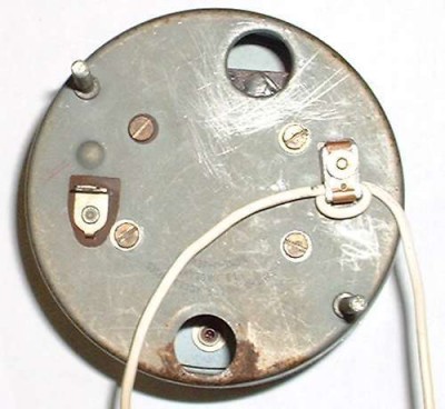
White wire from ignition switch to the tach where it makes a little loop then to the + side of the coil.
Red wire from electronic ignition to + side of the coil.
Black wire from electronic ignition to the - side of the coil.
In this configuration, the engine runs but the tach doesn't work. The tach does also have 12v going to a terminal on the back, and when I turn the key off, there's a slight click and the tach needle bounces slightly.

I tried looping the wire in the other direction behind the tach, no difference.

Some reading says that the white wire needs to go to the negative of the coil. Well, I tried that and surprise surprise, no spark so no running engine since the coil and hence the ignition never receive 12v on the positive side. More reading indicates that yes, the white wire should go to the + on the coil.

Doing some research, I've seen mention of powering the electronic ignition with its own dedicated 12V to cut down on tach wobble. That would mean...
White wire, ignition switch to tach to + side of the coil.
Red wire, from fusebox to electronic ignition
Black wire, from ground to electronic ignition
But that leaves nothing on the - side of the coil? Or should the black wire from the ignition go there instead of a direct ground? Or should it also get a direct ground?

I've also seen mention of grounding the case of the coil itself. Should that be done?

Finally, I have heard conflicting reports on whether the tach itself needs further modification (meaning, another bit of circuitry inside) to work with a Powerspark or similar electronic ignition? Maybe that's my problem all along? But I want to wire everything in the best way possible so I'm still trying to figure out the other questions.

Thanks folks!

Re: Tach, coil, Powerspark wiring

PostPosted: Tue Jul 20, 2021 10:01 pm
by mbell
I believe you currently have it wired correctly for a standard tacho. You don't mention a ground on the tacho? Is that an oversight in your description or is it really missing?

A separate power supply for the electronic ignition is generally a good idea but not required. You may get inaccurate readings with out it thou. If you do that the module ground/black still connects to the coil negative.

It didn't hurt to ground the coil case but shouldn't be needed for the tacho to work.

My guess for the issue would be:
1) missing ground on tacho
2) not got the white wire correctly done on the tacho
3) faulty tacho

Re: Tach, coil, Powerspark wiring

PostPosted: Tue Jul 20, 2021 10:14 pm
by groucho
mbell wrote:I believe you currently have it wired correctly for a standard tacho. You don't mention a ground on the tacho? Is that an oversight in your description or is it really missing?

Well, the body of the tach is grounded through one of the posts, so that the lights work. Attached is a photo.
The spade terminal has 12V going to it. I believe that's correct - the original wiring diagram shows a wire from the first fuse to the tach as well as the white wire going through it, then to a snap connection, then to the coil. Curiously, the diagram does not show a color for that wire; I went with green as a standard switched power color. Generally I've tried to follow Lucas standard wire colors for everything including things that weren't originally present on the car, like the electric fan, electric fuel pump, etc.

Re: Tach, coil, Powerspark wiring

PostPosted: Wed Jul 21, 2021 1:08 am
by fotsyr
When the ignition is changed from points to electronic, the tach has to be modified.
chris

Re: Tach, coil, Powerspark wiring

PostPosted: Wed Jul 21, 2021 1:16 am
by rgh0
The white wire loop should go through and around the metal loop that sticks out the back in the early tacs, in your photo it looks like it is just wired beside it and retained with a plastic cable tie.?

cheers
Rohan

Re: Tach, coil, Powerspark wiring

PostPosted: Wed Jul 21, 2021 2:02 am
by groucho
rgh0 wrote:The white wire loop should go through and around the metal loop that sticks out the back in the early tacs, in your photo it looks like it is just wired beside it and retained with a plastic cable tie.?

cheers
Rohan

There's no cable tie but there is a small piece of plastic that the white wire loops through, with a "step" on it so it only fits in a certain way and a hole so it fits over the post. I had kept that plastic piece attached to the original white wire until putting in the new wire so that I could replicate the original loop as closely as possible - but it was a few years ago when it was originally removed. I tried flipping it so the plastic was pointing the other way with no difference. But you're right in that the loop currently doesn't go through the metal bracket that's holding the plastic piece in. Maybe it's just a matter of flipping the wire loop over so it goes through the metal loop instead of away from it...?

Re: Tach, coil, Powerspark wiring

PostPosted: Wed Jul 21, 2021 6:47 am
by HCA
Speed reading your opening post, I latch onto your bit that you rewired it for negative earth. How?

By the looks of it you are still running as an RVI and it should be RVC.

Apart from which, as Rohan notes, the rev counter will never work, even on the original points set up.

You need a board that converts your unit to RVC and negative earth.

Go into Spiyda https://spiyda.com/tachometer-wiring
and follow it from there. Get a new board from them or, better still, have them do it for you.

Re: Tach, coil, Powerspark wiring

PostPosted: Wed Jul 21, 2021 8:36 am
by Andy8421
rgh0 wrote:The white wire loop should go through and around the metal loop that sticks out the back in the early tacs, in your photo it looks like it is just wired beside it and retained with a plastic cable tie.?

cheers
Rohan

To expand on Rohan's point, the tach won't work as you have it connected. The white wire loop forms the primary of a pulse transformer, the secondary is inside the tach itself. What looks like a cheap bent metal U bracket (which it is) serves as the iron core of the transformer. If you unscrew the thumbwheel, the bracket pulls off allowing the loop to be placed next to the screw that the thumbwheel fits on, then the bracket is replaced with one leg through the loop, so effectively the loop wraps around the bracket.

A picture is worth a thousand words, I will see if I can find one.

edit: A few pictures down shows how to fit the loop around the bracket. Not exactly the same tach as an Elan, but the principle is the same. Link below.

2nd edit: The electronics in a Smiths tach are very rudimentary, effectively a poor man's frequency to voltage converter, with the tach display itself really just a voltmeter. The electronics was designed to be triggered by the current pulse from a standard coil/points setup. Some electronic ignitions generate pulses that can confuse the electronics, so if fixing the loop still doesn't work, check your ignition will work with a standard Smiths inductive loop tach.

https://mgaguru.com/mgtech/electric/et202c.htm

Re: Tach, coil, Powerspark wiring

PostPosted: Wed Jul 21, 2021 8:58 am
by ericbushby
Sorry HCA, but you are not correct there.
To change the polarity of an RVI, it is only necessary to change over the supply connections to the circuit board.
One is a wire and the other is a resistor (150 ohms I think) and they will both reach the new position with no alteration. It is written up somewhere on the internet and it works quite well. I have it somewhere, but it is over 10 years since I did mine.
To be reliable for use with an electronic ignition module the two ageing capacitors have to be replaced also.
It is quite simple to change them and they will cost maybe 50 pence each.
No separate 12 volt supply was necessary. It works quite well as originally wired.
It actually took me longer to get the glass out and remove the works than to do the conversion.
It is not a difficult job and as I had the capacitors anyway, it cost me nothing and works well.
When refitting the tacho the white wire has to pass through the pick up loop the opposite way to keep the input signal polarity correct for the electronics.
Eric in Burnley
1967 S3SE DHC

Re: Tach, coil, Powerspark wiring

PostPosted: Wed Jul 21, 2021 10:04 am
by Bigbaldybloke
I changed polarity on my Plus 2 many years ago and did similar to Eric in Burnley, just swopped the supply wires round inside the tacho, didn't even change the capacitors. this worked fine with the Lumenition optical ignition system I had fitted at the time. since then I've had a complete rebuild and rewire and changed to a Pertronix ignition system and am now having problems, the tacho reads, but not the correct reading, its approx twice what it should read. I got the small interface box from Spiyda but initially its still not reading correctly, i'm assuming its something to do with how I've got it wired. But that's my problem not yours, all I wanted to confirm is that to just change polarity the wiring mod inside the tacho is purely to swap over the supply wires from the case and power terminal. if capacitors look past their sell by date by all means change them, but its not strictly necessary. I think your problem is twofold, one the white loop wire looks incorrect as pointed out by Rohan and secondly you do need the Spiyda conversion, either internally which is neater or the external add on box which I have and am sure will work when i get around to it. There is a thread somewhere on here detailing the complete mod inside the tacho, but unless modifying electronic boards is something you are familiar with and competent at I'd give that option a miss.

Re: Tach, coil, Powerspark wiring

PostPosted: Wed Jul 21, 2021 1:03 pm
by groucho
Andy8421 wrote:edit: A few pictures down shows how to fit the loop around the bracket. Not exactly the same tach as an Elan, but the principle is the same. Link below.

Yes, those pictures look identical to how my tach wiring is, and I had kept the nylon piece on the wire like they describe. Looks like my reassembly wasn't right - funny how that happens when years go by between beginning and completing a job! :D

Bigbaldybloke wrote:But that's my problem not yours, all I wanted to confirm is that to just change polarity the wiring mod inside the tacho is purely to swap over the supply wires from the case and power terminal. if capacitors look past their sell by date by all means change them, but its not strictly necessary.

Yeah, I had swapped those two when converting, as described in the link that Andy put in. Attached is a photo from back when I did it. The green wire soldering looks horrible in the photo but it's not really that bad! I didn't look too closely at the caps but the ones in the photo don't look too bad, and the tach definitely worked before, just bouncy like so many are. At this point, I want to get it working and if it's still bouncy, I can work on making that better. Hence my questions about wiring the ignition direct and/or grounding the coil case.

I think your problem is twofold, one the white loop wire looks incorrect as pointed out by Rohan and secondly you do need the Spiyda conversion, either internally which is neater or the external add on box which I have and am sure will work when i get around to it. There is a thread somewhere on here detailing the complete mod inside the tacho, but unless modifying electronic boards is something you are familiar with and competent at I'd give that option a miss.

I'm not opposed to a Spiyda if necessary but it sounds like not one shouldn't prevent the tach from working at all? Sounds like Eric has good results with things as original other than swapping the wires and replacing some caps.

edit: Looking at the Spiyda, that's an RVI to RVC conversion, isn't it? I'm inclined to leave it RVI if possible.

Re: Tach, coil, Powerspark wiring

PostPosted: Thu Jul 22, 2021 2:48 pm
by stugilmour
Jeff, I struggled with the original tach with a Pertronix setup.

Finally got rhe tach converted by Nisonger and all good with both Pertronix and now MSD electronic ignition. I believe the conversion was about $250 and took about six weeks, including shipping to Canada.

Here is a link showing some details of their conversion. All wires are clearly marked on the converted tach. From memory you end up with a +12v supply, a signal wire, and a ground which I connected to one of the mounting posts. The tach works very well, compares closely with the remote tach that came with my timing light, and is very accurate when rpm is compared to GPS speed and the recalibrated speedometer. .

http://www.nisonger.com/electric-tachom ... rsions.htm

Just an option for you. Recommend the company and they are perhaps almost local to you.

Regarding the wiring questions, I agree the stock tach should work without grounding the coil case. Although I grounded my coil, I believe this was originally primarily part of the radio static suppression package in my Plus 2. Not sure if your Elan is similar.

1607413C-27BD-4223-BA7A-2B8AA801441A.jpeg and
From Section M - Electrical Equipment of the Plus 2 WSM. This page describes the radio suppression measures.


HTH

Re: Tach, coil, Powerspark wiring

PostPosted: Thu Jul 22, 2021 2:56 pm
by groucho
stugilmour wrote:Just an option for you. Recommend the company and they are perhaps almost local to you.

Yeah. I'm sure I can send the tach out and have a working one, but that seems like a last resort, hopefully I don't have to go that far! Hopefully just moving the loop will help. I will probably not be starting the engine before this weekend so I'll find out then. Once it's at least partially working, I'll see how much wobble there is and how desperate I am to fix it.

Regarding the wiring questions, I agree the stock tach should work without grounding the coil case. Although I grounded my coil, I believe this was originally primarily part of the radio static suppression package in my Plus 2. Not sure if your Elan is similar.

Interesting. There's definitely no radio suppression stuff on S2s, and it wouldn't bother me anyway since I have no radio in the car. :lol: I know some later small Elans did have some of the suppression equipment. I may end up grounding it anyway, just because "why not", it shouldn't hurt anything and can only help.

Re: Tach, coil, Powerspark wiring

PostPosted: Fri Jul 23, 2021 3:14 am
by groucho
One small update... turns out that getting the loop in the right place was just a matter of rotating the nylon piece the wire loops around 90 degrees. There's a small bump on top that lines up with a hole in the little metal bracket, so that's done!

Unfortunately, I can't test it because now I have no spark... I put all the wiring back how it was (white and red from the dizzy to the + on the coil, black from the dizzy to the coil) and nothing... I'm wondering if I fried the electronic ignition when I was testing things. I hope not but I'm not sure what else it could be! I have verified that I'm getting 12v to the coil... Sigh! I may end up putting the old distributor just to see what happens but I hate to screw around with timing again.

Re: Tach, coil, Powerspark wiring

PostPosted: Sat Jul 24, 2021 1:14 am
by billwill
rgh0 wrote:The white wire loop should go through and around the metal loop that sticks out the back in the early tacs, in your photo it looks like it is just wired beside it and retained with a plastic cable tie.?

cheers
Rohan


This is certainly one error, the white wire loop has to be around the iron/ steel u-shaped piece. THe U is half of a ring of iron/steel and acts as the 'core' of a transformer, inside the tacho is another coil of wire (maybe only one or two turns) which picks up the magnetic pulses that circulate in the 'core' and are created by the white wire loop.

This shows how it should be done.:
Image


In later versions of the tacho the white coil is also inside the tacho case so that you can't make that mistake, instead of the magnetic loop there are male & female bullet connectors on the back of the tacho and the white wire has a bullet junction at that point so you just pull the white wire into two and plug the two ends into the bullet connectors on the tacho.

Even so if you do not convert your tacho you will get a jittery needle unless the 12v power supply to the tacho comes from a point that is clean electricity, i.e not carrying the ignition pulses.

This topic seems to be the best one covering this matter:
viewtopic.php?t=44593&p=317481