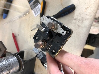
How to fix your starter solenoid
4 posts
• Page 1 of 1
So this work break's project was to change out the engine mounts as one collapsed (see other thread shortly). Went to start the car up to drive onto the low ramps to get a jack under it and the solenoid clicked strongly but wouldn't crank.
Did some poking around with the multimeter and found no continuity between the large terminals when the solenoid was energized. Did some googling and found someone here had recommended drilling out the rivets and giving the contacts a cleanup. Sorry I can't recall the name, nor find the thread! Couldn't find any pictures anywhere, so thought it may be useful for some others. I know its a $10 part, but I like fixing things where I can and it was worth a few hours of dicking about in the shed than just ordering one and waiting for it to turn up a week later
First up, remove the solenoid from the firewall. Take note of what goes where.
Turn the solenoid over and drill out the 4 rivets. I used a 3mm drillbit.
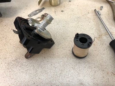
And this is what you'll find inside:
To get the coil off you need to desolder the joint on the top. I used a normal soldering iron and had a spring/plunger type desolder-er that worked very well. Gently remove the coil, and then the round metal plate with the notches in it along with a plastic gromet type thing. Can be seen below, but not a great photo.
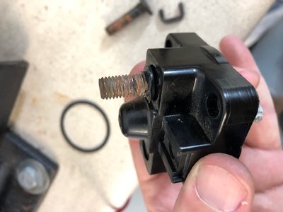
Next get the posts out which which was a bit tricky. Pushed from the threaded side, and back in again. This raised the rubber grommets enough to remove by hand. They got a tiny bit chewed up on the thread.
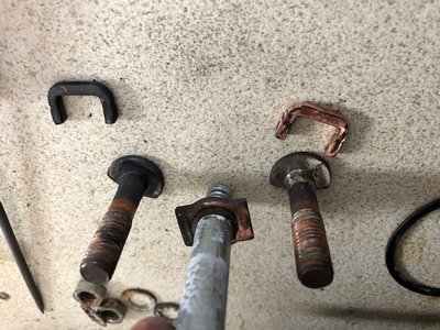
Then you can remove all the contacts from inside. Pretty simple. I gave them a clean up with a fine file. Bit of a before and after on one side compared to the other after a very quick clean. Very black! Couldn't even tell they were copper!
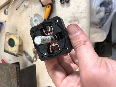
Put it all back together. Main plunger, then the little 'U' bits, then the posts. After then the notched plate and little grommet.
Then carefully put the coil back on and re-solder to the middle tab.
Before I put the rubber grommets back in around the posts I put a bit of black silicone in there to seal it up properly. I was a little worried it would cop a bit of water from rain/washing in it's normal position.
Then put the rubber seal back in between the two halves. Attach the two halves with M3x12mm bolts and nuts (I used SS as rusty bolts are the worst).
All done!
I was very happy with the results, my engine has never turned over better!
Chris
Elan +2 #0245
Exige S2 Supercharged
Elan +2 #0245
Exige S2 Supercharged
- Chrispy
- Third Gear

- Posts: 309
- Joined: 29 Oct 2017
Well done, I have to admit that I would probably have thrown it away and bought a replacement. The satisfaction of jobs like this makes it all worth while and your excellent write up will encourage the rest of us.
- mikealdren
- Coveted Fifth Gear

- Posts: 1194
- Joined: 26 Aug 2006
Chris
you forgot to mention turning the contactor bar upside down to use the " new" surface , not the old pitted one..
John
you forgot to mention turning the contactor bar upside down to use the " new" surface , not the old pitted one..
John
-

john.p.clegg - Coveted Fifth Gear

- Posts: 4533
- Joined: 21 Sep 2003
john.p.clegg wrote:Chris
you forgot to mention turning the contactor bar upside down to use the " new" surface , not the old pitted one..
John
I didn't even think of that
Chris
Elan +2 #0245
Exige S2 Supercharged
Elan +2 #0245
Exige S2 Supercharged
- Chrispy
- Third Gear

- Posts: 309
- Joined: 29 Oct 2017
4 posts
• Page 1 of 1
Total Online:
Users browsing this forum: shynsy and 29 guests


