Spare good distributor or coil for sale?
18 posts
• Page 1 of 2 • 1, 2
I am attempting to trace a fault that caused Toad to spend another trip on the breakdown truck.
lotus-twincam-f39/misfire-then-will-not-pull-hill-t40445.html
I've stripped apart the fuel pump and carb. filters and all seems fine.
It is fitted with an accuspark electronic distributor.
Anyone have a good spare distributor or coil I could have to eliminate the next suspects.
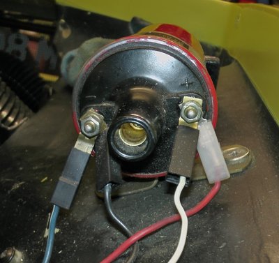
The coil is also wired somewhat strangely. What is the blue / yellow wire on the negative.
The power comes from the thin white wire that is connected to the tacho! That has to be wrong surely?
Remember the Spyder connection. Anything is possible.
According to the workshop manual the coil is supplied from the solenoid. I take it this was changed.
Where should it come from on an S130?
- vincereynard
- Coveted Fifth Gear

- Posts: 1240
- Joined: 12 Jan 2015
Does it have a RVC tacho fitted? (does your tacho stop if you unplug it??)
I'm not a fan of Accuspark ignitions, i've had a number of them fail and have heard if the thermal paste isn't done well under the module they overheat and break down quite quickly...... That said mine just stopped working rather than played up.
If it helps i have a Ballast coil i could send you? I might have a 12v Lucas coil too but i'd have to check.....
Chris
-

Grizzly - Coveted Fifth Gear

- Posts: 2023
- Joined: 13 Jun 2010
I agree with Grizzy the Blue/Yellow is probably the sense wire for a RVC tacho.
There are two power sources as standard. A white wire from the ignition that goes to the tacho and then to the coil, Quite possibly to a blast resistor to provide ~9V. On a standard RVI tacho the power line should be routed through the tacho so it can sense current for the tacho to work. With an updated RVC tacho the connections used just be connected behind the dash.
The second power, white/yellow, is from the solenoid to the coil and this is only powered when the starter is engaged. This provides the full "12v" to the coil and bypasses the ballast to improve starting.
vincereynard wrote: According to the workshop manual the coil is supplied from the solenoid. I take it this was changed.
Where should it come from on an S130?
There are two power sources as standard. A white wire from the ignition that goes to the tacho and then to the coil, Quite possibly to a blast resistor to provide ~9V. On a standard RVI tacho the power line should be routed through the tacho so it can sense current for the tacho to work. With an updated RVC tacho the connections used just be connected behind the dash.
The second power, white/yellow, is from the solenoid to the coil and this is only powered when the starter is engaged. This provides the full "12v" to the coil and bypasses the ballast to improve starting.
'73 +2 130/5 RHD, now on the road and very slowly rolling though a "restoration"
- mbell
- Coveted Fifth Gear

- Posts: 2704
- Joined: 07 Jun 2013
vincereynard wrote:The coil is also wired somewhat strangely. What is the blue / yellow wire on the negative.
The power comes from the thin white wire that is connected to the tacho! That has to be wrong surely?
Remember the Spyder connection. Anything is possible.
According to the workshop manual the coil is supplied from the solenoid. I take it this was changed.
Where should it come from on an S130?
Original RVI tacho's wiring is;
White wire; (un-fused) from ignition switch to tacho, through sense loop inside tacho & then from tacho to coil + terminal providing ignition feed to coil (via ballast resistor if you have one).
Green wire; (fused ignition switched +) from fuse box to tacho.
Black wire; - (earth) to tacho
If your tach has been converted to RVC type, usually done as RVI types sometimes read erratically after an electronic ignition conversion, then your wiring should be;
White wire; disconnected from tacho & joined so going direct from ignition switch to coil +. (or ballast resistor).
Green wire; as above
Black wire; as above
NEW WIRE; sense wire from coil - terminal to tacho (possibly the Blue/yellow wire you have)
If you have a ballast resistor you will then have a White/yellow wire from solenoid to coil, by-passing the ballast resistor to give the coil full 12v when cranking. This should only be live when the solenoid, & therefore the starter, is engaged. at all other times, coil is fed reduced voltage from the ballast resistor & requires the correct ballast type coil to work correctly.
Original coil wiring is essentially;
White wire; ignition feed to + terminal, via ballast resistor if fitted.
White/Yellow wire; Ballast resistor by-pass feed to + terminal (only if ballast resistor fitted)
White/Black wire; Distributor points to coil - terminal
As you have an electronic conversion, the Black/White wire will have been discarded & replaced with the Black wire from your ignition module.
The Red wire from your module needs an un-resisted 12v supply. This can be picked up from the coil + terminal (as in your photo) provided you don't have a ballast resistor. If you do have a ballast resistor in the circuit, it should be connected to the input side of the resistor or any other ignition switched live.
HTH, Tim
- Orsom Weels
- Third Gear

- Posts: 480
- Joined: 31 Oct 2011
If thats a red Accuspark sports coil it's 12v 3.0ohm (not a Ballast)......... Might be wrong but i thought all the later +2's had a ballast set up??
I don't think the Blue/White wire will be the hot wire from the Starter solenoid for the simple reason it should bypass the Ballast and hit the 6v coil with 12v on cranking (basically over juicing the coil to get a much stronger spark when the starter is running) if the hot wire was connected to the - on the coil i suspect it would not start (might kill your Ignition module too)
I don't think the Blue/White wire will be the hot wire from the Starter solenoid for the simple reason it should bypass the Ballast and hit the 6v coil with 12v on cranking (basically over juicing the coil to get a much stronger spark when the starter is running) if the hot wire was connected to the - on the coil i suspect it would not start (might kill your Ignition module too)
Chris
-

Grizzly - Coveted Fifth Gear

- Posts: 2023
- Joined: 13 Jun 2010
Grizzly wrote:I don't think the Blue/White wire will be the hot wire from the Starter solenoid
I don't think anyone has suggested it is ? It's most likely a new wire added to provide the signal sense for an RVC type tacho.
Grizzly wrote:it should bypass the Ballast and hit the 6v coil with 12v on cranking (basically over juicing the coil to get a much stronger spark when the starter is running) if the hot wire was connected to the - on the coil i suspect it would not start (might kill your Ignition module too)
I suspect you're spot on, if you tried to feed 12v+ into the - of the accuspark unit, it would most likely do it no good at all
Regards, Tim
PS, I think you're also right about S130's all having a ballast resistor as standard.
- Orsom Weels
- Third Gear

- Posts: 480
- Joined: 31 Oct 2011
Tim, I was replying to this 'According to the workshop manual the coil is supplied from the solenoid. I take it this was changed. Where should it come from on an S130?' (Confusing as the quote didn't attach to my reply)
I assume there isn't an external Rev Limiter box fitted? as they often ground the - to cut the ignition when the target RPM is achieved?
I assume there isn't an external Rev Limiter box fitted? as they often ground the - to cut the ignition when the target RPM is achieved?
Chris
-

Grizzly - Coveted Fifth Gear

- Posts: 2023
- Joined: 13 Jun 2010
Correct on all counts gentlemen.
The tacho has a note on it from speedycables - replace in 1989
It is an accuspark sports coil hiding in a Lucas ballast coil holder.
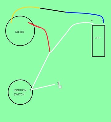
Yellow goes to negative (eventually) on coil.
Red goes, via No2 on ignition switch, to positive on coil.
See awful diagram.
Perhaps the coil or module is damaged? No way of knowing. The coil shows 2.9 ohms so that's within spec for a non ballast coil.
I may replace the ignition module with dear old points as at least they work and eliminate one potential problem. Small problem is finding a tiny screw to hold the ballast resistor! ?3 the set!
http://www.simonbbc.com/points/lucas-25 ... 466ecb525d
- vincereynard
- Coveted Fifth Gear

- Posts: 1240
- Joined: 12 Jan 2015
Just to be sure : condenser and ballast are 2 different components. Condenser is actually a capacitor, that you need to dampen the coil discharge oscillations. Ballast is a resistor, that you only need when you have a 2 mode coil, cranking under 12V and operation under about 9V. Apparently you don't have a 2 mode coil, since it is 2.9 Ohms, so you should not have a ballast.
S4SE 36/8198
-

nmauduit - Coveted Fifth Gear

- Posts: 2044
- Joined: 02 Sep 2013
So am i correct in saying they wired the tacho up using the white wire as a power on it's way to the Coil when they did the RVC conversion? On mine i just connected the two white wires together (bypassing the Tacho and removed the anti theft switch at the same time) then used a separate power from the voltage stabiliser to power the Tacho.
Chris
-

Grizzly - Coveted Fifth Gear

- Posts: 2023
- Joined: 13 Jun 2010
then used a separate power from the voltage stabiliser to power the Tacho.
The tacho has its own stabalizer zener diode inside and does not need a stabalized supply.
It DEFINITELY does not need a feed from an original 10 volt stabalizer, because those are actually vibrators which go from 0 to 12 volt and vice versa rapidly to create an AVERAGE output of 10 volts. Fine for thermal instruments but hell for a tacho.
Bill Williams
36/6725 S3 Coupe OGU108E Yellow over Black.
36/6725 S3 Coupe OGU108E Yellow over Black.
- billwill
- Coveted Fifth Gear

- Posts: 5062
- Joined: 19 Apr 2008
Vince
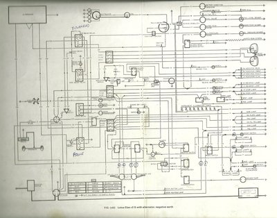
See attached for a +2S Wiring diag, the s130 is the same for ignition
Can you fit a set of points to rule out the Accuspark ?
Good luck with your problem
See attached for a +2S Wiring diag, the s130 is the same for ignition
Can you fit a set of points to rule out the Accuspark ?
Good luck with your problem
John
+2s130 1971
+2s130 1971
-

Hawksfield - Fourth Gear

- Posts: 601
- Joined: 14 Jul 2004
billwill wrote:then used a separate power from the voltage stabiliser to power the Tacho.
The tacho has its own stabalizer zener diode inside and does not need a stabalized supply.
It DEFINITELY does not need a feed from an original 10 volt stabalizer, because those are actually vibrators which go from 0 to 12 volt and vice versa rapidly to create an AVERAGE output of 10 volts. Fine for thermal instruments but hell for a tacho.
Funny you say that, it was pointed out i didn't add a new power supply to my Tacho when i did the RVC conversion, the power came from the 12v power 'B Battery' of the voltage stabiliser 100% (on my 2 seater).
Like this....
Chris
-

Grizzly - Coveted Fifth Gear

- Posts: 2023
- Joined: 13 Jun 2010
Hawksfield wrote:Vince
Can you fit a set of points to rule out the Accuspark ?
I had seriously considered that, especially at only ?3 the set. The first problem is where to source the tiny screw that holds the condenser in place. It all just takes more time.
Anyway I've gone the whole way.
Huco pump
https://www.dellorto.co.uk/shop/car-acc ... ump-133010 Note it is especially recommended for Weber and Dellorto. No need for pressure regulator. It may get an inertia switch if it behaves!
powerspark ignition and new coil.
http://www.simonbbc.com/bundle-deals/el ... ement-coil
I shall also renew the column switch to coil wiring - just in case.
I am doubtful about accuspark stuff. A brand new, posh, accuspark strobe only works occasionally.
- vincereynard
- Coveted Fifth Gear

- Posts: 1240
- Joined: 12 Jan 2015
18 posts
• Page 1 of 2 • 1, 2
Total Online:
Users browsing this forum: No registered users and 12 guests


