Page 1 of 1
Alternator conversion wiring

Posted:
Sun Mar 12, 2017 8:48 pmby 106500
I'm in the process of upgrading to an alternator on my S4 Elan. I'm slightly confused by the wiring arrangements.
There are 3 x wires from the Paul Matty connector to the alternator; 1 x Large Brown/White, 1 x Small Brown/Yellow and 1 x Small Brown (with 'ring' connector on the end). I have a RB 340 voltage regulator and as I understand it, the Large Brown 'output' goes to Terminal B (this will join the Large Brown and Large Brown and Blue cables on the existing B terminals (I'm planning to get a 'piggy back' connector as in effect there will be 3 x cables on terminal B - which only has 2 x spade connectors). The 1 x Small Brown/Yellow cable I will connect to terminal D (this is linked to terminal WL). However, I am uncertain what to do with the remaining 1 x Small Brown wire? Does this also go to terminal B on the regulator? I'd appreciate your thoughts please.
Re: Alternator conversion wiring
Posted:
Sun Mar 12, 2017 9:23 pmby mbell
Can't help with the rb340 connections but the wiring connections are likely main output, Dash warning light and regulator power. The regulator power should be connected to a switched live.
Re: Alternator conversion wiring
Posted:
Sun Mar 12, 2017 11:37 pmby billwill
Here's a topic about converting to Alternator.
lotus-electrical-f38/fitting-alternator-t14326.html?hilit=alternator%20circuitAnd Another:
lotus-electrical-f38/new-alternator-not-charging-batt-light-stays-t28734.html?hilit=alternator%20circuitThe internal circuit and the minimal external circuit is shown in this diagram on that topic:
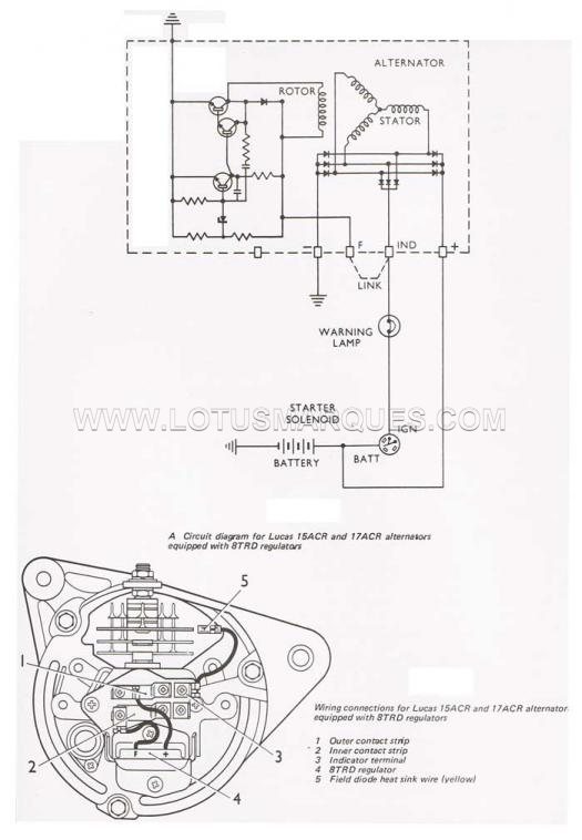
As you see the main output of the Alternator (+) goes straight to the battery. The other outputs (are usually linked inside the alternator) and go to the switched ignition circuit through the ignition warning light. (which must be a filament one, not LED). On switch on a small current passes through the bulb to energise the internal controller circuit and through that the field/rotor coil. When the alternator spins its output voltage increases until it is around 12 volts above ground on BOTH sides of the indicator bulb: so the bulb is not glowing.
The dynamo control box is not needed when an alternator is fitted, but many Elan owners use it as a handy terminal block to fasten the wires to. The FIRST topic mentioned, tells you which terminals can be used for this purpose
Re: Alternator conversion wiring
Posted:
Mon Mar 13, 2017 5:58 amby 106500
Thanks for the responses but I still am not quite clear where small brown wire (with a ring connector) from the alternator connecting 'loom' runs to. From what I can see it could go to the starter solenoid but it seems logical merely to run it to the 'B' terminal on the regulator being the same terminal as the main alternator output large brown wire is run to? As has been suggested, I'm using the old regulator as a terminal block.
Re: Alternator conversion wiring
Posted:
Mon Mar 13, 2017 9:16 amby nmauduit
I have installed a Lucas ACR 17 on my S4, leaving the box in place for the looks : wiring was rather straightforward, internally regulated alternator having essentially 2 connections, main (big brown and white and a small brown in your case apparently) to the positive battery live, and dash light (brown/yellow in your case). There is a dedicated plug one can use on ACR alternators, the two big ones are to the battery (B+ B+ on the plug), and I have routed them to the starter solenoid with quality brown wire; the small signal on the plug is usually labeled IND or D+.
In case of any doubt PM should provide a wiring diagram upon request.
Re: Alternator conversion wiring
Posted:
Mon Mar 13, 2017 3:55 pmby 106500
All, thanks for all your help. Everything is installed and working. However, one problem; at position one and two on the ignition key, the ignition light is lit (when I'd expect it not to be). At position three the light extinguishes but when starting the engine the light lights momentarily (as I'd expect to happen) and then extinguishes as the revs rise (again seems correct). It seems there is something amiss though at key positions one and two - everything else seems to be working including the tachometer. any ideas please?
Re: Alternator conversion wiring
Posted:
Mon Mar 13, 2017 4:21 pmby 106500
106500 wrote:All, thanks for all your help. Everything is installed and working. However, one problem; at position one and two on the ignition key, the ignition light is lit (when I'd expect it not to be). At position three the light extinguishes but when starting the engine the light lights momentarily (as I'd expect to happen) and then extinguishes as the revs rise (again seems correct). It seems there is something amiss though at key positions one and two - everything else seems to be working including the tachometer. any ideas please?
Sorry but just to add to the above, when I turn off my battery isolation switch and turn it on again, everything is normal (i.e. the ignition light is extinguished at positions one and two) until I start the engine - then it reverts to the ignition light remaining lit even when I remove the ignition key - strange!
Re: Alternator conversion wiring
Posted:
Mon Mar 13, 2017 5:03 pmby 106500
106500 wrote:106500 wrote:All, thanks for all your help. Everything is installed and working. However, one problem; at position one and two on the ignition key, the ignition light is lit (when I'd expect it not to be). At position three the light extinguishes but when starting the engine the light lights momentarily (as I'd expect to happen) and then extinguishes as the revs rise (again seems correct). It seems there is something amiss though at key positions one and two - everything else seems to be working including the tachometer. any ideas please?
Sorry but just to add to the above, when I turn off my battery isolation switch and turn it on again, everything is normal (i.e. the ignition light is extinguished at positions one and two) until I start the engine - then it reverts to the ignition light remaining lit even when I remove the ignition key - strange!
Apologies - all sorted now (left the earth wire connected to the regulator!)
Re: Alternator conversion wiring
Posted:
Mon Mar 13, 2017 7:31 pmby pharriso
After converting to an Alternator I wasn't happy with the old wiring just bundled up by the voltage regular:
So I have stripped out all the guts from the regulator & reconnected the original wiring:
Looks original & weighs a lot less, Colin would be happy.

Re: Alternator conversion wiring
Posted:
Sun Mar 19, 2017 2:24 pmby Boomer100E
In all likelihood, that second brown wire with the ring terminal is meant to connect directly to the battery terminal at the solenoid. I would think that its purpose is to bolster the existing brown wire in the loom (solenoid to control box) that is probably sized for the old dynamo at 44/0.3mm (25 Amps), and so not really up to the job of handling your new alternator's full output current. If the second wire is 28/0.3mm that would add a useful 17 Amps carrying capacity to the battery charging circuit.
Re: Alternator conversion wiring
Posted:
Sun Mar 19, 2017 2:51 pmby billwill
Are there any markings on the alternator body where the wires emerge, markings like the names in the diagram above. + - F Ind
 Viewed 2521 times")
 Viewed 2521 times")