
Elan Sprint Two pin Flasher unit
10 posts
• Page 1 of 1
![]() Post by: Type28 » Mon May 23, 2016 9:16 am
Post by: Type28 » Mon May 23, 2016 9:16 am
I have been changing the dash on my Elan Sprint whilst the engine was being rebuilt, it has taken Speedy Cables longer than the engine rebuild to renovate my Speedo (but that's another story).
I have searched the forum, but have not been able to find the answer to my problem, but did get a lot of other useful hints and tips.
Anyway whilst I was stripping out the dash I labelled everything and took a lot of pictures. When the dash was removed I noted a two pin flasher unit screwed to the back of the dash. I did not have a note of removing any wires from the unit and assumed it was redundant.
I have not been able to located another flasher unit on the car- I have looked under the crash pad, foot wells, under the bonnet area, so I am assuming that the two pin unit was still being used and that I somehow missed removing the wires from it ( although I am convinced I didn?t !).
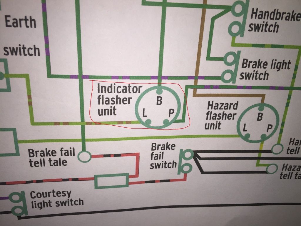
I have checked my work shop manual and various wiring diagrams and they all show the three pin flasher unit?
I down loaded a wiring diagram from the site, which has been very helpful
Two pin flasher unit
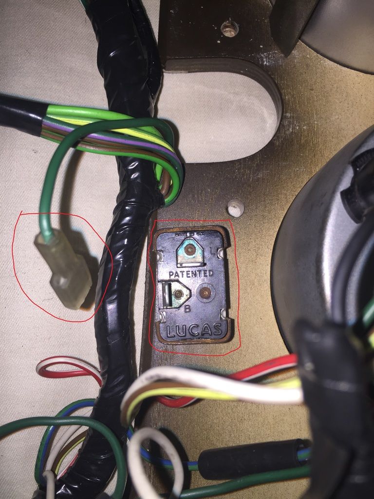
The flasher unit has pins marked L and B , the wiring diagrams all have three pin units marked L, B and P
I have found two spare wires Green/Brown and Green, which could be candidates for the flasher unit?
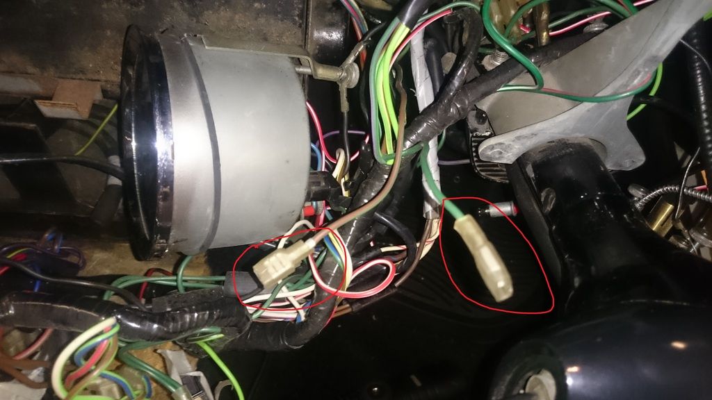
The green brown wire comes from the indicator stalk.
Any advice welcome as everything was working in the car when I removed the dash.
I have searched the forum, but have not been able to find the answer to my problem, but did get a lot of other useful hints and tips.
Anyway whilst I was stripping out the dash I labelled everything and took a lot of pictures. When the dash was removed I noted a two pin flasher unit screwed to the back of the dash. I did not have a note of removing any wires from the unit and assumed it was redundant.
I have not been able to located another flasher unit on the car- I have looked under the crash pad, foot wells, under the bonnet area, so I am assuming that the two pin unit was still being used and that I somehow missed removing the wires from it ( although I am convinced I didn?t !).
I have checked my work shop manual and various wiring diagrams and they all show the three pin flasher unit?
I down loaded a wiring diagram from the site, which has been very helpful
Two pin flasher unit

The flasher unit has pins marked L and B , the wiring diagrams all have three pin units marked L, B and P
I have found two spare wires Green/Brown and Green, which could be candidates for the flasher unit?


The green brown wire comes from the indicator stalk.
Any advice welcome as everything was working in the car when I removed the dash.
- Type28
- Second Gear

- Posts: 112
- Joined: 26 Dec 2013
![]() Post by: lotusS2guy » Mon May 23, 2016 6:22 pm
Post by: lotusS2guy » Mon May 23, 2016 6:22 pm
My Series 2 Elan definitely has a two-pin flasher mounted on the back of the dash next to the tacho.
Herb
26/4618
26/4618
-

lotusS2guy - Second Gear
- Posts: 99
- Joined: 05 Oct 2010

![]() Post by: pereirac » Tue May 24, 2016 1:08 am
Post by: pereirac » Tue May 24, 2016 1:08 am
My Sprint had a 2 pin flasher, for the indicators, held in a metal clip behind the dash.. I replaced it for a more modern electronic unit so my indicators now flash even when I have the headlights and fan on... 
Carl
Carl
-

pereirac - Fourth Gear

- Posts: 961
- Joined: 01 Oct 2003

![]() Post by: bob_rich » Tue May 24, 2016 10:31 am
Post by: bob_rich » Tue May 24, 2016 10:31 am
Hi
I have attached a scan of the just the indicators from my Elan +2S circuit
with a 2 pin flasher unit one connection G (green on +2S) goes to a ignition switched +12V via a fuse
the other LGN ( light green brown on +2S ) goes to the indicator stork common. This look like the colours you have spare.
with a test meter you can trace through the connection from the ignition switch ( or with ignition on and battery connected up you could use a simple side lamp bulb with the other end connectors to earth to determine the lead with the +12V applied) the other lead for the indicator switch can be traced through with the test meter on resistance or continuity function)
hope this helps best of luck
Bob
- Attachments
-
 Viewed 1664 times")
- bob_rich
- Fourth Gear
- Posts: 555
- Joined: 06 Aug 2009
![]() Post by: billwill » Tue May 24, 2016 3:00 pm
Post by: billwill » Tue May 24, 2016 3:00 pm
I'm pretty sure that the labels on the 3 terminal flasher B, L, P stand for:
B - Battery
L - Lamps
P - Panel
The P terminal was for the Panel (dashboard) indicator.
As Bob_Rich's diagram indicates, the panel light can instead be wired across the Left- to Right external indicator lamps. In this case which ever side is activated lighting the external lamps the voltage is also presented to the panel light. Current flows through it and then through the two external light bulbs of the external indicators, but there is not enough current for them to glow, but there is enough for the panel light to glow.
When wired this way the flasher does not need the third terminal P. However if you ever changed to LED bulbs on the external indicators, this arrangement might not work.
Bill Williams
36/6725 S3 Coupe OGU108E Yellow over Black.
36/6725 S3 Coupe OGU108E Yellow over Black.
- billwill
- Coveted Fifth Gear

- Posts: 4417
- Joined: 19 Apr 2008
![]() Post by: Ross Robbins » Tue May 24, 2016 5:38 pm
Post by: Ross Robbins » Tue May 24, 2016 5:38 pm
I hope I am not hijacking this thread 
Here goes: I was concerned about the dimness of the brake lights and running lights on my Plus 2 so I replaced the 1157 bulbs with LED bulbs. I am elated with the brightness of the brake and running lights, but now my turn signals don't work. I understand that the LED doesn't draw enough current to operate a standard flasher unit and I see where Carl has replaced his with an electronic flasher unit which is what has been recommended to me.
So, here is the question: What flasher unit is it Carl? Part number and maker please. And do I also need a separate one for the hazard flasher per Bob Rich's diagram? And what is that part number?
Or is it better to add a resistor or two and leave the current flashers in place? If yes, what size resistance is needed and how is it wired in? Thanks to all of you who understand this stuff better than I do, which is all of you
- Ross Robbins
- Third Gear

- Posts: 298
- Joined: 03 Apr 2006
![]() Post by: billwill » Tue May 24, 2016 7:09 pm
Post by: billwill » Tue May 24, 2016 7:09 pm
Ross,
Given that the standard flasher goes into rapid mode when a single external indicator bulb blows, it implies that you need the load equivalent to two light bulbs to make a standard flasher work properly.
Indicator bulbs are usually 12v 21 watt. Each LED bulb probably uses about 2 watts, so the required resistive load is about 2x21-2x2 or 38 watts at 12 volts
This corresponds to a resistor of about 3.8 ohms, say 4 ohms as a purchased unit.
It will get VERY hot so a rating of about 50 watts would be needed, it will probably be enclosed in a metal heatsink.
All in all it would be better to fit an electronic replacement flasher.
Bill Williams
36/6725 S3 Coupe OGU108E Yellow over Black.
36/6725 S3 Coupe OGU108E Yellow over Black.
- billwill
- Coveted Fifth Gear
- Posts: 4417
- Joined: 19 Apr 2008
![]() Post by: Type28 » Sat May 28, 2016 8:33 pm
Post by: Type28 » Sat May 28, 2016 8:33 pm
Well I have got the dash back in the car and the indicators are Woking and the green indicator light works both left and right. What worries me is that I didn't realise that I had disconnected the wires from the flasher unit. 
- Type28
- Second Gear
- Posts: 112
- Joined: 26 Dec 2013
10 posts
• Page 1 of 1
Total Online:
Users browsing this forum: No registered users and 15 guests