Page 1 of 1

Voltage Stabilizer Wiring

PostPosted: Wed Jan 28, 2015 11:15 am
by William2
I am rewiring my S4 dash with a new loom and have a question to ask about the voltage stabilizer wires. The workshop manual shows a green wire from the "B" terminal to what looks like the ground metalwork of the speedometer. Is this correct? The body of the VS is also grounded to the metalwork presumably?

Re: Voltage Stabilizer Wiring

PostPosted: Wed Jan 28, 2015 11:58 am
by billwill
This diagram shows the basic wiring of most classic cars.

The voltage regulator reduces the variable 12v-14v battery voltage to an average 10 volts steady, for feeding those instruments which are voltage sensitive. On our Elans that is only the fuel gauge and the water Temp gauge of a Plus 2.

The regulator has an input an output and an earth. Exactly how thoat is achieved may vary.

Image

Image

~~~~~~~~~~~~~~~~~~~~~

Editing Note: the image vanished so I I have edited the message to show an alternative copy of the classic instrument circuit.

Re: Voltage Stabilizer Wiring

PostPosted: Wed Jan 28, 2015 4:14 pm
by stugilmour
The B terminal means 'Battery' and the I terminal means 'Instruments'. The unit is grounded thru the case lug, which is sort of represented in Bill's diagram by the 'E' or 'Earth' on the lug loop.

As Bill mentions the actual wire colours used may vary by model. Typically Green is 'Hot in Run/Start - Fused', and would power the voltage stabilizer using the B terminal. This varies though; my Plus 2 powers the stabilizer with White 'Hot in Run/Start - Unfused'.

The wire carrying the 10v supply from the stabilizer to the instrument(s) varies by model. Not a big deal as it is confined to the dash board anyway.

You definitely do not want a Green running to ground! The diagram may be trying to indicate the Speedo power terminal?

I found this document helpful for the stabilizer.

http://www.mossmotors.com/graphics/prod ... 31-555.pdf

HTH

Stu

Re: Voltage Stabilizer Wiring

PostPosted: Sat Apr 25, 2015 4:41 am
by mayanktanwar
A voltage stabilizer is an electrical appliance used to feed constant voltage current to electrical gadgets like AC and computers, and protects them from damage due to voltage failure. I have not much knowledge about voltage wiring, the installation of voltage stabilizer(http://www.batterybhai.com/category/vol ... bilizers/5) is done by electricians.

Re: Voltage Stabilizer Wiring

PostPosted: Sun Nov 13, 2022 4:31 pm
by collins_dan
So I have been through the archives and want to confirm my conclusion. My 1970 S4 the fuel gauge recently started to only show empty when engine off, full when engine on. I checked all connections and all are good. I suspect the voltage stabilizer needs to be replaced. My only question is that I have a five spade unit, my first spade connection is a white green wire, then next to it are the two green wires, number 3 spade has nothing, number for four has one green wire and number 5 has nothing. I don’t see a white green wire on the wiring diagram, I see green black. What gives? Please confirm that I should replace and what is the significance of white green vs green black. Does it just signify unfused instead of fused? Thanks, Dan

Re: Voltage Stabilizer Wiring

PostPosted: Sun Nov 13, 2022 8:01 pm
by billwill
It's quite important to realise that the mechanical old-type 'voltage stabilizer' on our old cars DOES NOT PROVIDE A STEADY 10 VOLT OUTPUT; instead it switches the battery voltage (11 to 14.5 volts) on and off so that the AVERAGE output is 10 volts.

As such it is only suitable for use with slow instruments, i.e those which work by bending bi-metallic strips. Some fuel gauges work by opposing magnetic fields so are quick and not suitable for use with old-style mechanical stabilizers.

There are modern electronic chips which do take in a variable battery voltage and then output a steady 10 volt power supply. It is probably best to replace old-type stabilizers with modern electronic ones when the old ones fail.

Re: Voltage Stabilizer Wiring

PostPosted: Mon Nov 14, 2022 9:18 am
by HCA
collins_dan wrote:So I have been through the archives and want to confirm my conclusion. My 1970 S4 the fuel gauge recently started to only show empty when engine off, full when engine on. I checked all connections and all are good. I suspect the voltage stabilizer needs to be replaced. My only question is that I have a five spade unit, my first spade connection is a white green wire, then next to it are the two green wires, number 3 spade has nothing, number for four has one green wire and number 5 has nothing. I don’t see a white green wire on the wiring diagram, I see green black. What gives? Please confirm that I should replace and what is the significance of white green vs green black. Does it just signify unfused instead of fused? Thanks, Dan


It is all laid out clearly and correctly by Stu two posts back from yours.

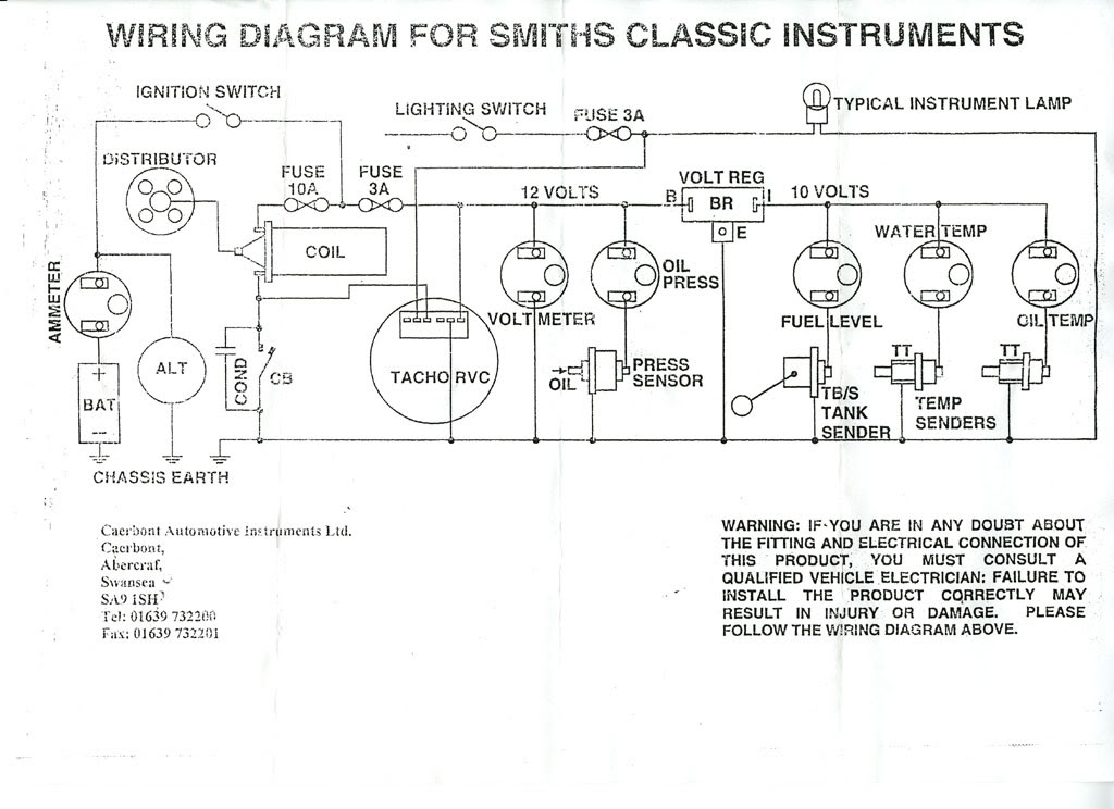
saying you have a 5 spade unit is not very clear. Regardless of how many spades and putting numbers to them, you must refer to the terminals B and I (and possibly E or a ground symbol if fitted).

Lotus wiring colours mean nothing.

The convention though is for White/Green to be used where there is a second fuel pump...(Green/White though is RH indicator lamps). Have you, per chance, a second fuel pump that a PO might have done the right thing using a G/W wire and used the spare spade on the stabilser for switched power...only a guess. If not, then it is anyone's guess what the wire is doing! You will have to trace it I fear!

The Green/Black you see on the diagram should be fuel gauge to tank sender...

With ignition switch on, check for voltage out of any of the green wires that you have. One, maybe two, should show 12V (plus or minus half a volt) This or these wires should be on the 'B' of your new stabiliser (suggest you get a modern one instead of an original)

The green wires that do not show voltage should be on the 'I' terminal of the stabiliser - double check that these wires go to 'B' or + terminals of your fuel and water gauges.

The stabiliser might have a terminal marked 'E' or with a ground symbol - this is to earth.

To answer your question as to what is fused or unfused - complicated. On early UK cars, simply assume everything is unfused except Green or for many switches, where Green is the major colour. Wiring has moved on a long way since those days! Motto is to be careful of every colour - test twice and connect once!

Re: Voltage Stabilizer Wiring

PostPosted: Mon Nov 14, 2022 2:19 pm
by elanner
collins_dan wrote:My 1970 S4 the fuel gauge recently started to only show empty when engine off, full when engine on. I checked all connections and all are good. I suspect the voltage stabilizer needs to be replaced.


This sounds more like the sender than the stabilizer. Have you checked its (the sender's) resistance?

Nick

Re: Voltage Stabilizer Wiring

PostPosted: Mon Nov 14, 2022 4:46 pm
by Andy8421
Dan,

5 connections are a surprise (some Smiths stabilisers did have a separate earth terminal marked 'E' instead of relying on the case as an earth, though not usually on the Elan). A picture of the installation would help.

Your sender should have a resistance of 230 ohms empty, 30 ohms full if you want to do a quick check on the sender to see if that has shorted out.

A dud voltage regulator will have the gauge reading high relative to where it should be, but not full all the time.

Good luck.

edit: Thinking about it, I am interested where 5 spade terminals would fit. Link below to the details of the stabiliser.

https://www.merlinmotorsport.co.uk/files/transfer/technical/doc/voltagestabiliserinst.pdf

Re: Voltage Stabilizer Wiring

PostPosted: Mon Nov 14, 2022 8:52 pm
by Baggy2
We're not getting the voltage regulator (otherwise known as control box ) and voltage stabiliser confused here are we? That has 5 terminals. I've never seen a voltage stabiliser with 5 terminals.

Re: Voltage Stabilizer Wiring

PostPosted: Mon Nov 14, 2022 8:53 pm
by Baggy2
We're not getting the voltage regulator (otherwise known as control box ) and voltage stabiliser confused here are we? That has 5 terminals. I've never seen a voltage stabiliser with 5 terminals.

Re: Voltage Stabilizer Wiring

PostPosted: Tue Nov 15, 2022 12:11 am
by smo17003
The photo in this thread shows the 5 terminal VS that has been mentioned
viewtopic.php?t=21145&p=124798

I think it is as simple as the E is earth (ground) for vehicles where the VS is not attached directly to an earthed component.
The B and I are both "siamesed" terminals, so in effect there are only 3 terminals.
For the B you have a feed from the battery to one of its terminals. The other B terminal then provides a battery feed to a subsequent component, thereby reducing the amount of wiring.
The two I's would then feed, if required, two separate components.
The above could all be wrong, but that's how I see it.

I used one of the electronic versions on my S4 (see below from Ebay). Some suppliers also offer to rebuild your old metal cased VS with new electronic internals if you prefer.

https://www.ebay.co.uk/itm/282642726457 ... Sw9opfhCfU

Mike

Re: Voltage Stabilizer Wiring

PostPosted: Wed Nov 16, 2022 2:32 pm
by collins_dan
Thanks for the comments. I tried to get a pic, but it's not much help (attached) and I am not ready to start pulling things out just yet. If it is time to replace, I will use the BEI connections per Stu's post as I am sure that is how it is currently wired. The white green will be a challenge to trace as it goes right into the loom. It's not a big deal. It likely the input from the sender. I was just curious. It sounds like the fact that it is only showing full or empty is not necessarily an indication that the voltage stabilizer is the culprit. Could be the float is jammed. It's one of the few places in the car that I have not explored and I am not anxious to explore it. Is there any special technique for tapping in the right location to unjam it, similar to float on strombergs? Thanks for any additional insight. Dan