
the c40 dynamo and its pulley
42 posts
• Page 3 of 3 • 1, 2, 3
![]() Post by: billwill » Tue Nov 18, 2014 10:58 pm
Post by: billwill » Tue Nov 18, 2014 10:58 pm
Galwaylotus wrote:billwill wrote:This seems ODD, since the spark is generated when the points open not close, the coil isn't actually connected to earth at that time.
If it wasn't there would be no spark!! The HT side of the coil puts out some 15k volts but voltage is a potential and to spark it has to find its way to earth. In this case that's via the distributor and spark plug. The points break the primary circuit (low voltage) allowing the secondary side (high voltage) to come into effect when the field collapses generating a voltage.
One side of the high tension coil must in fact be earthed somehow either through the case or through the low tension coil, But the latter would only work if the contact breaker was on the live side of the low tension coil and I've never heard of such an arrangement. All distributors that I have known, one side of the contact breaker is connected to the distributor case & thus to the engine and so there would be no way to arrange that the contact breaker is on the live side of the coil.
Hence it MUST BE that the low end of the high tension coil is connected to the ignition coil case. I can see that some people might think it was not connected if they used an ohm meter on a low ohm range to check continuity between the high tension output and the coil case. This is because the resistance of the high tension coil is relatively high (it has lots and lots of turns on the winding) so you need to use a high ohm range to check continuity between the high tension lead output and the case of the ignition coil.
This article shows the way, I think that an ignition coil works and you can see that the high tension coil is connected to the case at the low end.
http://www.hemmings.com/hmn/stories/200 ... ure33.html

<later>
HMMM, there are far too many diagrams to ignore on the internet that show the low end of the high tension coil connected internally to the low end of the low tension coil. I can't at this stage, see how that would work, because as I said a few messages ago, the contact breaker is opened to cause a spark, so at that point in time the bottom end of the high tension coil is not connected to earth and via that to the case of the spark plugs. I would not expect the condensor to be rated to handle the 15Kv or so of the spark voltage and I would not expect it to have enough capacity to hold the whole energy required for the spark.
Very puzzling ??? Sometime soon I will use my ohm meter to checks my ignition coil on my Elan and then report back.
Bill Williams
36/6725 S3 Coupe OGU108E Yellow over Black.
36/6725 S3 Coupe OGU108E Yellow over Black.
- billwill
- Coveted Fifth Gear

- Posts: 5062
- Joined: 19 Apr 2008
![]() Post by: Galwaylotus » Wed Nov 19, 2014 12:03 pm
Post by: Galwaylotus » Wed Nov 19, 2014 12:03 pm
Error in my earlier post. There is connectivity between each of the terminals on the coil as in the lower figure in billwill's post. Current flows through the primary circuit as long as the contact points are closed. The secondary circuit (high voltage) is open at that time as there is no connection through the distributor. When the points open, the rotor is adjacent to a post in the distributor cap. As the magnetic field collapses, a voltage is induced in the secondary winding and its only path to earth is via the coil HT terminal, HT lead to the distributor, rotor to post, spark plug lead from distributor cap post to spark plug and across the plug gap to the engine and back through the earthing system. There is no connection in any of my coils between the metal casing and any of the coil terminals, +, -, or HT. That indicates that there is no need to earth the coil casing. I have relocated the coil in my Elan by means of a fabricated fibreglass bracket and the engine runs in spite of the coil casing not being earthed.
Coil resistance is identical in each circuit no matter in which direction it's measured. In my check this morning I measured 3.5 ohm through the primary circuit and the same with the leads of my multimeter reversed. The secondary circuit (either + or - post to HT socket) gives a reading of 6800 ohms and again no matter which way the leads are connected nor to which primary terminal, + or - , they are connected.
Coil resistance is identical in each circuit no matter in which direction it's measured. In my check this morning I measured 3.5 ohm through the primary circuit and the same with the leads of my multimeter reversed. The secondary circuit (either + or - post to HT socket) gives a reading of 6800 ohms and again no matter which way the leads are connected nor to which primary terminal, + or - , they are connected.
Mechanical Engineer, happily retired!
'67 S3 SE FHC
See Facebook page: W J Barry Photography
Put your money where your mouse is, click on "Support LotusElan.net" below.
'67 S3 SE FHC
See Facebook page: W J Barry Photography
Put your money where your mouse is, click on "Support LotusElan.net" below.
-

Galwaylotus - Coveted Fifth Gear
- Posts: 1348
- Joined: 01 May 2006

![]() Post by: rgh0 » Wed Nov 19, 2014 1:05 pm
Post by: rgh0 » Wed Nov 19, 2014 1:05 pm
I put a voltage on my spare coils today to determine what low voltage terminal the secondary high voltage coil internal end was connected to. Buy measuring the voltage at the high voltage terminal versus each low voltage terminal you can then figure out which lv terminal it is connected to
In an old Lucas coil it was to the CB terminal in newer Bosch coils it was to the +ve terminal
No connection to the casing in any of the coils.
cheers
Rohan
In an old Lucas coil it was to the CB terminal in newer Bosch coils it was to the +ve terminal
No connection to the casing in any of the coils.
cheers
Rohan
-

rgh0 - Coveted Fifth Gear
- Posts: 8831
- Joined: 22 Sep 2003

![]() Post by: BabyDriver » Wed Nov 19, 2014 7:33 pm
Post by: BabyDriver » Wed Nov 19, 2014 7:33 pm
I hope you don't mind a slight aside but is your dynamo a C40 or a C40L. My S4 has a C40L which is about 1/2" longer than the C40. I found this out when I borrowed the one off my Austin Healey Sprite which was a C40 which meant it wouldn't fit the bracket on the Elan. I presume the C40L is correct for the S4?
- BabyDriver
- New-tral
- Posts: 6
- Joined: 03 Dec 2013
![]() Post by: robertverhey » Wed Nov 19, 2014 8:40 pm
Post by: robertverhey » Wed Nov 19, 2014 8:40 pm
Interesting thread. When I converted my s3 to neg earth and fitted accuspark at the same time, a flier came with the accuspark kit (which I can't find now) about ensuring that the coil is connected the right way around so that the spark is "pushed" rather than "pulled" in the high tension circuit. The flier described the same test as is described in this article
http://mgaguru.com/mgtech/ignition/ig104.htm
As my coil had "cb" and "sw" labels on the spade terminals (instead of "+" and "-") I switched these around, I also made sure the coil is earthed.....maybe that wasn't essential after reading this thread, not too sure now.
Haven't performed the spark direction test yet, will get around to it in due course.
- robertverhey
- Fourth Gear

- Posts: 766
- Joined: 20 Feb 2007
![]() Post by: Craven » Thu Nov 20, 2014 12:19 am
Post by: Craven » Thu Nov 20, 2014 12:19 am
Hi
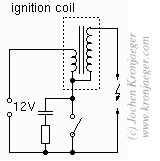
Have not read through all of this tread BUT in the discussion on the connection of the high voltage winding on an ignition coil it would seem it?s operation is not fully understood, the low side of the winding is connected internally to terminal that is connected to the contact breaker which has a CAPACITOR across it and it?s through this the HT winding is connected to chassis or return path, Google Kettering System for a more full explanation.
Here is what Wiki says:
At the same time, current exits the coil's primary winding and begins to charge up the capacitor ("condenser") that lies across the now-open breaker points. This capacitor and the coil?s primary windings form an oscillating LC circuit. This LC circuit produces a damped, oscillating current which bounces energy between the capacitor?s electric field and the ignition coil?s magnetic field. The oscillating current in the coil?s primary, which produces an oscillating magnetic field in the coil, extends the high voltage pulse at the output of the secondary windings. This high voltage thus continues beyond the time of the initial field collapse pulse. The oscillation continues until the circuit?s energy is consumed.
Ron.
- Craven
- Coveted Fifth Gear
- Posts: 1634
- Joined: 14 Sep 2013
![]() Post by: Quart Meg Miles » Thu Nov 20, 2014 8:44 pm
Post by: Quart Meg Miles » Thu Nov 20, 2014 8:44 pm
Without the condenser (capacitor) the spark would be very high and very short but have little energy. The engine might start but won't give any power, as I observed on a friend's motorbike. When the cb opens the condenser absorbs the current from the coil and the voltage ramps up in a controlled manner to peak at the optimum for the spark plug before its resonance with the coil brings it down again. The resonance/oscillation is only a few cycles long and quickly decays.
There is much talk about the correct polarity of spark which is interesting in light of some modern cars where coils are wired between pairs of spark plugs on different cylinders and there is no distributor spark gap. The plugs, therefore, have opposite polarity sparks.
Galway: I'm surprised you can measure a resistance difference of 0.05%! If the coil's secondary really does measure the same to both CB and SW (or + and -) terminals then its internal end must be connected to a centre tap of the primary and always get a slight boost from the CB's voltage change, the return path being the battery via the SW terminal. It doesn't really matter which end of the primary it attaches too but you will get a shock off the CB if you touch it as it rises to over 600 volts; it blew up my oscilloscope probe which was only rated at 500V!
The coil case is insulated but may give a mild shock if touched unless it is earthed, depending how the coil is wound and connected.
Meg
26/4088 1965 S1½ Old and scruffy but in perfect working order; the car too.
________________Put your money where your mouse is, click on "Support LotusElan.net" below.
26/4088 1965 S1½ Old and scruffy but in perfect working order; the car too.
________________Put your money where your mouse is, click on "Support LotusElan.net" below.
-

Quart Meg Miles - Coveted Fifth Gear
- Posts: 1278
- Joined: 03 Oct 2012

![]() Post by: dgym » Thu Nov 20, 2014 10:58 pm
Post by: dgym » Thu Nov 20, 2014 10:58 pm
Baby Driver,
my car has the shorter C40 , the car is from Dec 1966.
Everyone else, thanks for all the posts,
I am concerned about that magical 15% loss of spark, and I'm confused as to whether the coil that's now on my car is internally different to the one that came with it. The markings being + and - instead of CB and SW.
So, the way I'm seeing it now, I want + to go to the distributor, and I should get my 15% of fame... I mean power.
or do I go out and find a CB SW coil for a positive earth car.
36/6612
1967 S3 Coupe (left the factory in 66)
original rego PPC 8E
original owner B.M. Wetherill ..are you out there?
1967 S3 Coupe (left the factory in 66)
original rego PPC 8E
original owner B.M. Wetherill ..are you out there?
-

dgym - Third Gear

- Posts: 358
- Joined: 05 Apr 2014
![]() Post by: AHM » Fri Nov 21, 2014 5:31 am
Post by: AHM » Fri Nov 21, 2014 5:31 am
It's pretty simple if you forget about "earth"
The white wire from the ignition switch has polarity. In your case - ve so it goes to the - terminal.
The wire from the distributor has the opposite polarity in your case + so it goes to the + terminal.
The only earth is from the coil clamp to the chassis.
The coils are all the same. The difference is that SW and CB would be the wrong way round if you change polarity so they changed the markings to - and +
- AHM
- Coveted Fifth Gear
- Posts: 1453
- Joined: 19 Apr 2004
![]() Post by: billwill » Fri Nov 21, 2014 9:43 am
Post by: billwill » Fri Nov 21, 2014 9:43 am
Heh, Heh, I've been reading all the internet descriptions of the ignition circuit with the common terminal
and nodding to myself saying.. Ah yes, "resonant circuit -- capacitor & Coil... Ringing... Better spark ... " Yes, that would work...
Only trouble is now I don't know how my own ignition works, because I don't have a capacitor. I have a very simple Maplins/Velleman transistor ignition, in which simply the distributor contacts drive the input of a fast switching power transistor which switches the primary coil current on and off.. But no capacitor across the transistor.
 Puzzled of Muswell Hill
and nodding to myself saying.. Ah yes, "resonant circuit -- capacitor & Coil... Ringing... Better spark ... " Yes, that would work...
Only trouble is now I don't know how my own ignition works, because I don't have a capacitor. I have a very simple Maplins/Velleman transistor ignition, in which simply the distributor contacts drive the input of a fast switching power transistor which switches the primary coil current on and off.. But no capacitor across the transistor.
Bill Williams
36/6725 S3 Coupe OGU108E Yellow over Black.
36/6725 S3 Coupe OGU108E Yellow over Black.
- billwill
- Coveted Fifth Gear
- Posts: 5062
- Joined: 19 Apr 2008
![]() Post by: Craven » Fri Nov 21, 2014 11:44 am
Post by: Craven » Fri Nov 21, 2014 11:44 am
Hi,
Bill, you talked yourself out of the correct circuit analyse by thinking the capacitor in the distributor needed to have a very high voltage rating. The high voltage pulse developed across the series secondary circuit is divided between the coil V XL & the capacitor V XC.
I use the Velleman ignition on my 1961 Norton, modified for positive earth & 6volts, if you still have the circuit diagram I think capacitor C1 0.22uf across T2 replaces the one in the distributor.
I believe the use of CB & SW was adopted to ensure when there was a mix of positive & negative earth vehicles around the internal low end of the HT winding did get connected to the capacitor in the distributor directly rather than the otherwise series reactance of the primary winding.
Later on when negative earth was universally adopted (anti-corrosion move) the ? marking indicating this was to be the chassis, negative battery, connection, via the CB.
Ron.
- Craven
- Coveted Fifth Gear
- Posts: 1634
- Joined: 14 Sep 2013
![]() Post by: rgh0 » Fri Nov 21, 2014 12:26 pm
Post by: rgh0 » Fri Nov 21, 2014 12:26 pm
"I believe the use of CB & SW was adopted to ensure when there was a mix of positive & negative earth vehicles around the internal low end of the HT winding did get connected to the capacitor in the distributor directly rather than the otherwise series reactance of the primary winding."
All my modern coils have the secondary internally connected to the +ve terminal of the primary so the path to the capacitor for the inductance / capacitance oscillation is via the primary winding and to the -ve termal to the points and capacitor
cheers
Rohan
All my modern coils have the secondary internally connected to the +ve terminal of the primary so the path to the capacitor for the inductance / capacitance oscillation is via the primary winding and to the -ve termal to the points and capacitor
cheers
Rohan
-
rgh0 - Coveted Fifth Gear
- Posts: 8831
- Joined: 22 Sep 2003
42 posts
• Page 3 of 3 • 1, 2, 3
Total Online:
Users browsing this forum: No registered users and 21 guests