Voltage Stabilizer

Posted:
Tue Sep 02, 2014 1:05 pmby William2
Can anyone tell me what the correct type and part number is for the instrument voltage stabilizer and also the correct place to fit it on an S4 Elan?
Re: Voltage Stabilizer

Posted:
Tue Sep 02, 2014 2:50 pmby pharriso
Not sure of the correct original part number, but belongs here:
Do yourself a favour & buy a solid state one from Moss Motors, part number is 131-555... Instruction sheet attached
Re: Voltage Stabilizer

Posted:
Tue Sep 02, 2014 6:02 pmby Esprit2
Voltage stabilizers are available in 5 volt versions for use in 6 volt systems, and 10 volt versions for 12 volt systems. Then they're available in polarities for positive or negative ground systems. Finally, there are sub-sets of versions with internal or external grounds, and extra terminals. Electrically, the extra terminals are the same, just multiples to facilitate connecting more wires.
The voltage stabilizer needs to be grounded to work. Without a good ground, the voltage stabilizer will simply pass full system voltage through to the instruments, and the readings will be high and variable.
An internally grounded stabilizer needs to be mounted to a grounded metal surface, like the back side of the tach or speedo, as shown in Phil's photo), or must have a separate ground wire connected to the mounting screw.
An externally grounded stabilizer will have an additional spade terminal marked 'E' for Earth (ie, ground). Connect a separate ground wire there.
The Europa used similar instruments and voltage stabilizers, and in that Workshop Manual, it specified that the stabilizer should be mounted with it's long axis vertical, +/- 10 degrees. I can't explain the relevance of that, but I've always followed that spec.
The Smiths instruments have a non-linear response to ambient temperature, meaning the readings may vary slightly with seasonal temperature changes. However, the voltage stabilizer also has a non-linear response to ambient temp that is opposite that of the instruments. As long as the old instruments are used with the old 'mechanical' voltage stabilizer, one non-linearity cancels the other, and the read out should be pretty consistent regardless of season or ambient temperature.
Modern solid state voltage stabilizers produce a very constant voltage that doesn't vary significantly with ambient temp. If you convert to one of them, there may be a small seasonal variation in gauge readings. It's not a large variation, and is perhaps only of interest to theorists. And if the car spends it's Winters in storage, it's not an issue. I'm just throwing that out there so you know.
I suggest you purchase a replacement from a Lotus specialist in order to remove any mystery about selecting the correct one. If you're not willing to do that for some reason, then just select one of the correct voltage and polarity for your car, and make certain it's well grounded as installed... add a separate ground wire if required. After that, just re-connect the wiring per the labeled spade terminals. It's really no more complicated than that.
Terminals:
B Terminal to "B"attery, via Fuse Block.
I Terminal to "I"nstruments (usually Fuel & Temp).
E Terminal to "E"arth or Ground.
Good luck,
Tim Engel
Re: Voltage Stabilizer

Posted:
Tue Sep 02, 2014 7:24 pmby elanner
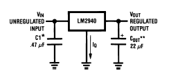
If you don't want to purchase an electronic stabiliser they are very easy to build for just a few bucks. Just three components: an LM2940T-10 and a couple of capacitors. I built mine in a old flasher can, which has a little more room than an original stabiliser.

- lm2940.png (6.02 KiB) Viewed 1369 times
Nick