This is how Colin described it in words for those who prefer them to a circuit diagram:
fatboyoz wrote:Tony,
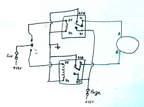
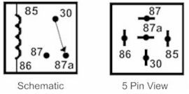
This is how I did the window conversion to relays. You will need two relays per window with the following connections: 30, 85, 86, 87 and 87a.
Follow this procedure per door:
30: Main power out of the relay to power motor. One to the up side of the motor and one to the down. (trial and error will figure that one out).
85: Up control signal from the window switch to the up relay and down control signal from the window switch to the down relay. (These wires are the ones that power the motors pre modification).
86 & 87a: These should all be bussed together and go to earth. The earth wire that presently goes to the motor case should be a suitable earthing point.
87: Power to the relays. I used a thicker wire for this. I took a feed from the main power into the car (thick brown/blue wire, part of main loom where it connects to the interior loom) located above passenger's (L/H seat) knees. This is unswitched and unfused. I then ran this single feed to a fuse box (two fuses) that I attached to the underside of the horizontal part of the firewall above the passenger's knees. Two 10 amp fuses and an individual feed to each door completes the power supply.
My doors have speaker holes cut into them, so I was able to gain access to the inside of the doors to wire up the relays and then mount them inside and up out of any water that might get inside the doors.
Colin.
Now as the further discussion has revealed, this description is correct for the original POSITIVE EARTH arrangement of the Elans, but if your car has been converted to NEGATIVE EARTH it is best to swap over the functions of Pins 85 and 86, in case the relays contain diodes.
This means that for negative earth with diodes Colin's instructions would read as follows instead, with some additional editing by me for clarity.:
You will need two relays per window with the following connections: 30, 85, 86, 87 and 87a.
Follow this procedure per door:
30: Main power out of the relay to power the window motor. One relay pin 30 to the up side of the motor and the other relay pin 30 to the down side. (trial and error will figure that one out).
86: The wires from the dash-board window switch. One wire goes to pin 86 on one relay and the other wire goes to pin 86 on the other relay. (These wires are the ones that power the motors pre modification).
85 & 87a: These should all be bussed together and go to earth on both relays, so you make up a lead with 4 connector on the relay end for this. The earth wire that presently goes to the motor case should also be connected to this, and connect it to the chassis or the black earthing wire that earths all the instruments behind the dashboard.
87: +12v Power to the window motors via the relays. Pin 87 of both relays connected together and then the other end connected to a suitable power source via an in-line fuse capsule.