Electric headlamp conversion.
21 posts
• Page 1 of 2 • 1, 2
Although this topic has been covered many times in the past, when I mentioned the conversion in an unrelated thread, there was some interest in me posting details. Indeed I am always happy to read new posts on old subjects, something of interest often turns up. So here goes. Firstly I would like to acknowledge all previous posters on this subject, upon which my conversion was based. The only thing new, I believe, is the use of the headlight retractor unit to enable headlamp flashing. Flashing can be achieved by wiring a diode between the main and dipped beam feeds. This is an elegant solution used by MX5 owners without the flash facility. It does however place the total load of motor, main and dipped beam on the column stalk switch and feed which may or may not be detrimental. Also the stalk must be held long enough for the flash to take place above the bodywork. My solution required both the Mazda retractor unit and 3 relays (the 4th for dipped beam isn't strictly necessary ), which is a less than elegant! It will be interesting to possibly hear, from those more electrically competent than me, of a more elegant solution. Above all this was a fun project providing some geometrical and electrical challenges and works extremely well, so justifying the many hours spent on, in particular, the rarely used flash facility!
The car is a 1973 Plus 2 S130/5, so the mechanical conversion is to the failsafe, with balance bar, variant.
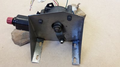
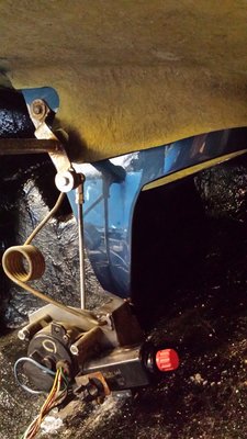
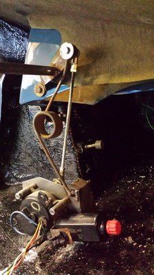
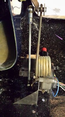
Both the motor and the retractor unit were from a Mazda MX5. I opted to mount the motor on the left side and utilise the existing balance bar lever. The motor arm is splined to the spindle so can easily be rotated to suit the mounted orientation of the motor.
The movement required to raise and lower the pods is governed by the relationship between the length of the arm on the motor and the length of the actuating lever on the balance bar. I opted to leave the motor arm as found and alter the actuating lever to suit since this is a straightforward cut n shut job.
This .pdf shows the relationship between the motor arm and the balance bar levers, also the calculations I did to determine the required length for the balance bar actuating lever.
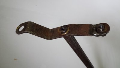
The actuating lever was cut to size and welded leaving the existing pivot tube which was sleeved and threaded to accept a ball joint one side and a bolt on the other.
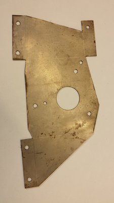
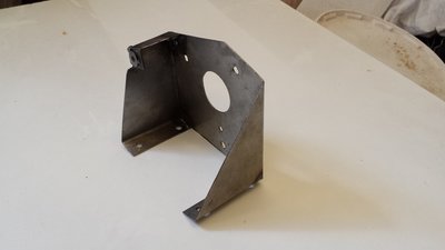
Next up fabricating a bracket.
The motor assembly must be mounted such that it's spindle is in line with an imaginary line drawn through the actuating lever pivot tube when in fully raised and fully lowered position. The motor arm must be moved to align with this imaginary line also.
A threaded stainless steel rod with a ball joint on each end provides the link. The length of this rod is determined by the distance from motor arm to balance bar lever and any adjustment on the rod is merely to achieve the correct length. The range of movement of the pod is solely determined by the length of the motor arm and the length of the lever on the balance bar. One of the heavier springs is used to damp vibration of the pod when the mechanism is in it's dwell angle.
The wiring diagram and description of operation is in this .pdf file.
I hope all this doesn't waffle on too much. All the original calculations and wiring diagrams were of course scribbled on some dirty scraps of paper and the time found to tidy it all up has only been found due to confinement following a ski accident! This will also impact on the planned May launch date .
.
The car is a 1973 Plus 2 S130/5, so the mechanical conversion is to the failsafe, with balance bar, variant.
Both the motor and the retractor unit were from a Mazda MX5. I opted to mount the motor on the left side and utilise the existing balance bar lever. The motor arm is splined to the spindle so can easily be rotated to suit the mounted orientation of the motor.
The movement required to raise and lower the pods is governed by the relationship between the length of the arm on the motor and the length of the actuating lever on the balance bar. I opted to leave the motor arm as found and alter the actuating lever to suit since this is a straightforward cut n shut job.
This .pdf shows the relationship between the motor arm and the balance bar levers, also the calculations I did to determine the required length for the balance bar actuating lever.
The actuating lever was cut to size and welded leaving the existing pivot tube which was sleeved and threaded to accept a ball joint one side and a bolt on the other.
Next up fabricating a bracket.
The motor assembly must be mounted such that it's spindle is in line with an imaginary line drawn through the actuating lever pivot tube when in fully raised and fully lowered position. The motor arm must be moved to align with this imaginary line also.
A threaded stainless steel rod with a ball joint on each end provides the link. The length of this rod is determined by the distance from motor arm to balance bar lever and any adjustment on the rod is merely to achieve the correct length. The range of movement of the pod is solely determined by the length of the motor arm and the length of the lever on the balance bar. One of the heavier springs is used to damp vibration of the pod when the mechanism is in it's dwell angle.
The wiring diagram and description of operation is in this .pdf file.
I hope all this doesn't waffle on too much. All the original calculations and wiring diagrams were of course scribbled on some dirty scraps of paper and the time found to tidy it all up has only been found due to confinement following a ski accident! This will also impact on the planned May launch date
Last edited by dougal9887 on Fri Feb 13, 2015 7:05 pm, edited 2 times in total.
- dougal9887
- Third Gear

- Posts: 244
- Joined: 23 Aug 2013
If you twiddle the manual actuation rod when the lights are up does the motor engage and rip the skin off your fingers like on an MX5?
I found out this quirk by accident, a girlfriend had bought an import MK1 MX5 direct from the docks in Ireland, drove it back to Sussex, gave it a good clean up and then asked me to look at it because the lights were stuck in the up position.
I found the manual knob for the mechanism, turned it, lots the use of my fingers but could conclude that the motors had power too them and would kick in when the microswitch closed if you tried to lower them.
Then I discovered a push button on the Dashboard with a pictogram that looked like someone washing a light bulb, she was sheepish and said "I wondered what that was so I pushed it but nothing much happened"
- Chancer
- Coveted Fifth Gear

- Posts: 1133
- Joined: 20 Mar 2012
Nice write up and pictures, I like the solution of using one of the original springs to damp the closing of the lights, mine are a bit fierce on the way down and close with a noticeable bounce which can't be doing the pods a lot of good.
I didn't use any relays in my setup assuming that the motor already had relays, one wire requires constant 12v feed and two other wires control the relays for 2no 180 degree segments of rotation effectively up or down. I have it all running from a multi position rotating headlight switch on the dashboard.
I didn't use any relays in my setup assuming that the motor already had relays, one wire requires constant 12v feed and two other wires control the relays for 2no 180 degree segments of rotation effectively up or down. I have it all running from a multi position rotating headlight switch on the dashboard.
Kindest regards
Alan Thomas
Alan Thomas
-

Spyder fan - Coveted Fifth Gear

- Posts: 2019
- Joined: 11 Jun 2009
Hi Cancer,
Thanks for the tip. Next time I'm feeling masochistic I'll try that out
Hi Spyder fan,
How come I have checked the notes on the wiring diagram a zillion times, yet the second viewer finds the mistake I do of course mean 180 deg and will alter the file to this effect and hopefully get it changed before it's pointed out too many times!
One changeover relay would always be required to raise and lower the pods using the existing controls. With permanent live on common, dipped beam feed closes NO to power the up wire and dipped beam off close NC to power the down wire. The retractor unit provides this function but also acts as a timed latching relay to provide flash. The additional relays shown are merely used to provide the flash function from a brief pull on the column stalk!
Best regards
Dougal.
Thanks for the tip. Next time I'm feeling masochistic I'll try that out
Hi Spyder fan,
How come I have checked the notes on the wiring diagram a zillion times, yet the second viewer finds the mistake
One changeover relay would always be required to raise and lower the pods using the existing controls. With permanent live on common, dipped beam feed closes NO to power the up wire and dipped beam off close NC to power the down wire. The retractor unit provides this function but also acts as a timed latching relay to provide flash. The additional relays shown are merely used to provide the flash function from a brief pull on the column stalk!
Best regards
Dougal.
- dougal9887
- Third Gear

- Posts: 244
- Joined: 23 Aug 2013
Dougal9887
What a great article! Beautiful installation!
Please allow me two questions. 1) Do you by any chance have the plate dimensions that you made up for the mounting box , and 2) Do you know by any chance if the mounting box is the same for a regular Elan?
Many thanks,
Frank
What a great article! Beautiful installation!
Please allow me two questions. 1) Do you by any chance have the plate dimensions that you made up for the mounting box , and 2) Do you know by any chance if the mounting box is the same for a regular Elan?
Many thanks,
Frank
Famous Frank
67 Elan Coupe
66 Elan S2 SE
65 Elan S2
65 Elan 26R
69 S2 Europa
06 Elise
67 Barracuda
67 Elan Coupe
66 Elan S2 SE
65 Elan S2
65 Elan 26R
69 S2 Europa
06 Elise
67 Barracuda
-

Famous Frank - Fourth Gear

- Posts: 556
- Joined: 29 Apr 2004
Frank,
I may still have the template for the mounting bracket, in which case I'll note dimensions on it and post a photo. I imagine it would be suitable for an Elan as the fixing tabs at the base could be bent to suit and welded at the desired angle.
Dougal.
I may still have the template for the mounting bracket, in which case I'll note dimensions on it and post a photo. I imagine it would be suitable for an Elan as the fixing tabs at the base could be bent to suit and welded at the desired angle.
Dougal.
- dougal9887
- Third Gear

- Posts: 244
- Joined: 23 Aug 2013
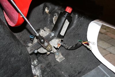
Frank, on the two seat Elan (I dare not say the "B" word) you are going to need twin motors as there is no balance bar across the car. I have done this using the same MX-5 (Miata) motors bought on ebay. I have dispensed with the vacuum knob inside the car and the microswitches at the pods. The lights are controlled with the lighting rocker switch only. First click puts on the side and tail lights, second click actuates the motors and switches on the main lights. Switching off the main lights lowers the pods automatically.
There is a single changeover relay to control the motors and it works really well. The only slight annoyance I have is that the headlights can only be flashed during the daytime if the dip switch is in the main beam position. I'm not clever enough to figure out a way to make it do it in the dip position. The pods come up and go down very smartly without bouncing and I have found that the original screw stops are not needed because the motor limits the movement effectively. I have no springs on mine. The linkage was carefully measured and made from threaded rod with small ball joint ends.
Mike
-

TroonSprint - Fourth Gear

- Posts: 507
- Joined: 24 Nov 2011
TroonSprint,
Thank you for info! I actually bought two Miata motors about a year ago in anticipation of performing this mod.
Your pic helped immensely.
Don't worry about no flashing ability. In the USA we just drive it like we stole it!!! No time for flashing.
Thank you,
Frank
Thank you for info! I actually bought two Miata motors about a year ago in anticipation of performing this mod.
Your pic helped immensely.
Don't worry about no flashing ability. In the USA we just drive it like we stole it!!! No time for flashing.
Thank you,
Frank
Famous Frank
67 Elan Coupe
66 Elan S2 SE
65 Elan S2
65 Elan 26R
69 S2 Europa
06 Elise
67 Barracuda
67 Elan Coupe
66 Elan S2 SE
65 Elan S2
65 Elan 26R
69 S2 Europa
06 Elise
67 Barracuda
-

Famous Frank - Fourth Gear

- Posts: 556
- Joined: 29 Apr 2004
Dougal, Do you still have the template for the mounting bracket. Sorry to ask, but I'm a lazy sort of guy that would rather copy than innovate! Yours do look very good.
Many thanks,
Frank
Many thanks,
Frank
Famous Frank
67 Elan Coupe
66 Elan S2 SE
65 Elan S2
65 Elan 26R
69 S2 Europa
06 Elise
67 Barracuda
67 Elan Coupe
66 Elan S2 SE
65 Elan S2
65 Elan 26R
69 S2 Europa
06 Elise
67 Barracuda
-

Famous Frank - Fourth Gear

- Posts: 556
- Joined: 29 Apr 2004
Frank, I've had another good look for the original template but no sign of it.
I could take a template from the prototype. Are you going to use a spring? If so I'd have to add the spring mounting to the template.
Dougal.
I could take a template from the prototype. Are you going to use a spring? If so I'd have to add the spring mounting to the template.
Dougal.
- dougal9887
- Third Gear

- Posts: 244
- Joined: 23 Aug 2013
Salut Dougal
I'd be very interested and grateful, too - with spring.
Merci
Vernon
I'd be very interested and grateful, too - with spring.
Merci
Vernon
-

vernon.taylor - Fourth Gear

- Posts: 683
- Joined: 05 Nov 2010
21 posts
• Page 1 of 2 • 1, 2
Total Online:
Users browsing this forum: No registered users and 3 guests

