Battery cut off switch
74 posts
• Page 4 of 5 • 1, 2, 3, 4, 5
On its own Meg,
"voltage ... only appears when a current is demanded by one of the circuits",
is an incorrect statement. The Voltage is there across the Battery terminals all the time (assuming it is charged). even if the battery is not connected to anything.
The confusion arises because that phrase should read: "voltage DROP... only appears when a current is demanded by one of the circuits",
The phrase basically relates to the portion of the supply voltage that you see across a component when a current is flowing in it.
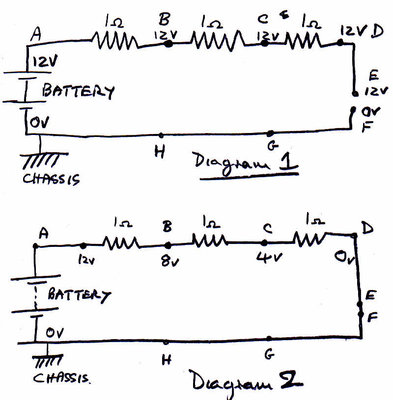
Imagine a simple circuit which has a 12 volt battery and three one ohm resistors connected in series, but with an open isolator switch in the negative side. This is Diagram 1 below.
While the isolator E-F is open, no current is flowing so because all of all of A,B,C,D and E are connected, all are at 12 volts relative to the chassis, hence the voltage drop across the second resistor B-C is 12v minus 12v i.e zero, which can be loosely described as "there is no voltage across resistor B-C".
However when you close the isolator switch E-F. A current of 12/3 i.e 4 amps will flow. The voltages relative to the chassis will then be as shown in diagram 2.
A at 12v, B at 8v, C at 4v, D at 0 v. So the voltage across B-C is (8 volts minus 4 volts) i.e 4 volts. so you could loosely say that the 4 volts across B-C appeared when the current flowed. {actually it's the other way around, the 4 volts CAUSED the current to flow.}
Bill Williams
36/6725 S3 Coupe OGU108E Yellow over Black.
36/6725 S3 Coupe OGU108E Yellow over Black.
- billwill
- Coveted Fifth Gear

- Posts: 5062
- Joined: 19 Apr 2008
A problem with your explanation, Bill, is that the Battery isolator is not between E & F as you've drawn it, it is between the chassis and the battery negative. That is to say; the Isolated terminal is actually the battery negative and all loads attach, ultimately, to the chassis. This must be where the discussion is breaking down.
So when no switch is actuated (which I can't sketch quickly), selecting a load, the battery is isolated at both ends and is truly floating so no voltage can be measured at the Isolated terminal. But once a switch is closed the battery positive (in this case) takes up chassis potential, as it can't drive a current round any loop, and its negative terminal appears as -12V on the Isolated terminal.
{And the current wasn't caused by the 4 volts, it was the result of the current being able to flow round the completed path and dropping that voltage across the resistor.}
No wonder we've got a horse meat problem in this country, it's Bill and I flogging them to death!
Meg
26/4088 1965 S1½ Old and scruffy but in perfect working order; the car too.
________________Put your money where your mouse is, click on "Support LotusElan.net" below.
26/4088 1965 S1½ Old and scruffy but in perfect working order; the car too.
________________Put your money where your mouse is, click on "Support LotusElan.net" below.
-

Quart Meg Miles - Coveted Fifth Gear

- Posts: 1278
- Joined: 03 Oct 2012
Quart Meg Miles wrote:A problem with your explanation, Bill, is that the Battery isolator is not between E & F as you've drawn it, it is between the chassis and the battery negative. That is to say; the Isolated terminal is actually the battery negative and all loads attach, ultimately, to the chassis. This must be where the discussion is breaking down.
So when no switch is actuated (which I can't sketch quickly), selecting a load, the battery is isolated at both ends and is truly floating so no voltage can be measured at the Isolated terminal. But once a switch is closed the battery positive (in this case) takes up chassis potential, as it can't drive a current round any loop, and its negative terminal appears as -12V on the Isolated terminal.
Agreed. my example was intended to illustrate voltage drop in general not the specific case.
Quart Meg Miles wrote:{And the current wasn't caused by the 4 volts, it was the result of the current being able to flow round the completed path and dropping that voltage across the resistor.}
Not agreed. the current is caused by the 4 volts or more strictly speaking: the 12 volt electric potential produced by chemicals in the battery, cause electrons to flow to the ends of the wires (a very very brief occurrence) from the negative end of the battery, if those wire ends are in turn connected to the positive end of the battery, the electrons continue to run round & round until the chemicals are exhausted. For any given portion of the circuit the potential between the ends of that portion cause the current to flow. The amount of current is determined by the resistance (the difficulty for the electrons to flow) and the portion of the driving force (supply voltage) available for that portion of the circuit. This is best understood with the water-flow analogy which is well explained in the book that I referenced above.
Volts are never a consequence of current, current is a consequence of volts.
Bill Williams
36/6725 S3 Coupe OGU108E Yellow over Black.
36/6725 S3 Coupe OGU108E Yellow over Black.
- billwill
- Coveted Fifth Gear

- Posts: 5062
- Joined: 19 Apr 2008
MickG wrote:Aren?t the circuits connected in parallel and not series as illustrated, so that the voltage is constant throughout the system?
Yes, Mick, Bill was writing a primer rather than illustrating the Elan which is why I wrote my last post. The voltage/current dispute is chicken and egg and we're done!
Incidentally, Biil, your earlier computation with a meter had an error: 12V at 120uA doesn't compute to 1 MOhm but your principle is correct.
Personally I'm not going to the hassle of a fuse but will make a 1 Amp current limiting bypass just for the courtesy lamp. On the 26 the battery is behind the LH seat, next to a chassis bolt for a (+ve) ground lead isolator.
Meg
26/4088 1965 S1½ Old and scruffy but in perfect working order; the car too.
________________Put your money where your mouse is, click on "Support LotusElan.net" below.
26/4088 1965 S1½ Old and scruffy but in perfect working order; the car too.
________________Put your money where your mouse is, click on "Support LotusElan.net" below.
-

Quart Meg Miles - Coveted Fifth Gear

- Posts: 1278
- Joined: 03 Oct 2012
Hi,
The relay I used was bought from RS and can be found here,http://uk.rs-online.com/web/p/latching-relays/6900808/
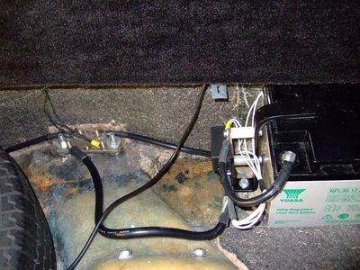
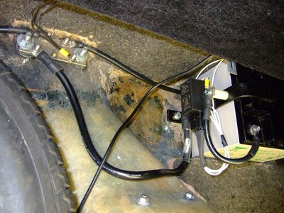
Maximum DC switching current 190A, latching relay with two operating coils. I installed a sprung loaded centre position switch, on-off-on, to operate the coils as these only need a fraction of a second to operate. The supply for the switch is taken from one of the permently live feeds behind the dash, the earth for the coils connected to the battery side of the breaker. I positioned the relay to break the circuit between the battery negative and the first earthing point in the boot.
A couple of pictures below.
Chris.
Are you really isolating the battery through a relay, including the starter current? Post details of the relay, please!
The relay I used was bought from RS and can be found here,http://uk.rs-online.com/web/p/latching-relays/6900808/
Maximum DC switching current 190A, latching relay with two operating coils. I installed a sprung loaded centre position switch, on-off-on, to operate the coils as these only need a fraction of a second to operate. The supply for the switch is taken from one of the permently live feeds behind the dash, the earth for the coils connected to the battery side of the breaker. I positioned the relay to break the circuit between the battery negative and the first earthing point in the boot.
A couple of pictures below.
Chris.
-

tcsoar - Third Gear

- Posts: 360
- Joined: 01 May 2007
Chris,
I have asked the question on cable size, now I have seen a picture of your earth cables, from battery to floor stud, can you tell me what size they are please. Mine is a 16mm2 welding cable but it seems very small compared to yours.
Paul
I have asked the question on cable size, now I have seen a picture of your earth cables, from battery to floor stud, can you tell me what size they are please. Mine is a 16mm2 welding cable but it seems very small compared to yours.
Paul
Kick the tyres and light them fires...!!!!!!!
- pauljones
- Fourth Gear

- Posts: 901
- Joined: 09 Feb 2008
Hi Paul,
From the relay to the earth bar I installed 35mm, this was a battery cable I had, its strands are similar to welding cable but has different insulation which makes it less flexible.
The cable from the battery to the relay is only 16mm, I intend to change this to 35mm when I get the correct lugs.
Chris.
-

tcsoar - Third Gear

- Posts: 360
- Joined: 01 May 2007
Well thought out, Chris, and thanks for the link though I think I'll stay manual switched on my S2.
Meg
26/4088 1965 S1½ Old and scruffy but in perfect working order; the car too.
________________Put your money where your mouse is, click on "Support LotusElan.net" below.
26/4088 1965 S1½ Old and scruffy but in perfect working order; the car too.
________________Put your money where your mouse is, click on "Support LotusElan.net" below.
-

Quart Meg Miles - Coveted Fifth Gear

- Posts: 1278
- Joined: 03 Oct 2012
Is it just me or does some nasa geeks have taken over this forum?!
Geeez you lost me at page 1
Geeez you lost me at page 1
Cooled down by CliveyBoy!
-

Pistacchio sprint 72 - Fourth Gear

- Posts: 735
- Joined: 12 Sep 2012
Thanks Paul,
As I have a +2 the only way I could fit a manual switch that I could reach from the drivers seat would have been under the dash and I didn't fancy that. I also didn't want to put a manual switch in the boot as I know that I would get lazy and not bother using it .
.
I was looking for an easy solution to isolate the battery as I got out of the car and as a bonus add a little bit of security.
Chris.
As I have a +2 the only way I could fit a manual switch that I could reach from the drivers seat would have been under the dash and I didn't fancy that. I also didn't want to put a manual switch in the boot as I know that I would get lazy and not bother using it
I was looking for an easy solution to isolate the battery as I got out of the car and as a bonus add a little bit of security.
Chris.
-

tcsoar - Third Gear

- Posts: 360
- Joined: 01 May 2007
Pistachio recently opened a thread but 10 minutes searching using all variations of the phrase was a failure so apologies for starting a new one.
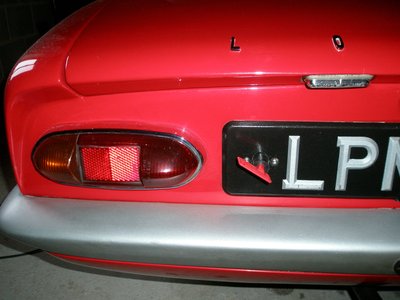
This thread prompted me to get around to fitting one but where? Rear bulkhead is convenient and reachable but inaccessible from the outside in the event of an accident and vulnerable to say, luggage. damage. Front wing needs more wiring and body drilling. So, a compromise, easy and cheaply reversible;
Jim
- jimj
- Coveted Fifth Gear

- Posts: 1119
- Joined: 25 Feb 2008
74 posts
• Page 4 of 5 • 1, 2, 3, 4, 5
Total Online:
Users browsing this forum: No registered users and 1 guest


