Installing Amp Meter properly
32 posts
• Page 2 of 3 • 1, 2, 3
The S2 used a +ve earth dynamo so a 30-0-30 Amp meter would be better. I fitted mine (in the dash) in the early 70s by fitting a high current mating pair of Lucar connectors to the ammeter's wires (male to -ve terminal, female to +ve) then threaded them through a new grommet in the "firewall" near the solenoid. I unplugged the brown wire Lucar from the solenoid and plugged it into the ammeter's male and plugged the ammeter's female onto the solenoid. Easy, though work out the wire lengths before crimping on the Lucars.
To return to standard simply unplug and refit the brown wire back on the solenoid.
To return to standard simply unplug and refit the brown wire back on the solenoid.
Meg
26/4088 1965 S1½ Old and scruffy but in perfect working order; the car too.
________________Put your money where your mouse is, click on "Support LotusElan.net" below.
26/4088 1965 S1½ Old and scruffy but in perfect working order; the car too.
________________Put your money where your mouse is, click on "Support LotusElan.net" below.
-

Quart Meg Miles - Coveted Fifth Gear

- Posts: 1170
- Joined: 03 Oct 2012
>>everything but horn and starter<<
uhh, no
it is pretty clear on the +2, the heavy brown wire feeds from the battery terminal on the solenoid directly to the ammeter.
everything but the high current side of the starter goes through the ammeter
this horn business is malarky
uhh, no
it is pretty clear on the +2, the heavy brown wire feeds from the battery terminal on the solenoid directly to the ammeter.
everything but the high current side of the starter goes through the ammeter
this horn business is malarky
- gus
- Fourth Gear

- Posts: 729
- Joined: 05 May 2011
Accommodating the high transient current required by the horn compromises the usefulness of the ammeter. Were as a 30 ? 0 ? 30 with associated resolution could be used, routing the horn feed through the meter requires perhaps 50 ? 0 ? 50 amp reducing the resolution to near half.
The inrush of start current to the compressor of air horns is very high and best served by lowest resistance path possible.
FWIW
Ron.
The inrush of start current to the compressor of air horns is very high and best served by lowest resistance path possible.
FWIW
Ron.
- Craven
- Coveted Fifth Gear

- Posts: 1624
- Joined: 14 Sep 2013
except they don't do it
all power is routed through the fuse box and fed by the ammeter in both the +2[which I own] and Europa[which I just checked]
http://images.lotuselan.net/lel/27204/0 ... 0RB106.jpg
horn relay fed from fusebox
dunno on +2, but my Exige has a 7 amp fuse for the horn
all power is routed through the fuse box and fed by the ammeter in both the +2[which I own] and Europa[which I just checked]
http://images.lotuselan.net/lel/27204/0 ... 0RB106.jpg
horn relay fed from fusebox
dunno on +2, but my Exige has a 7 amp fuse for the horn
- gus
- Fourth Gear

- Posts: 729
- Joined: 05 May 2011
Craven wrote:Because Lotus don?t do it doesn?t mean it?s not good practice.
BTW, I?ve been designing, drawing and reading electronic circuits for the last 50 yrs.
Ron.
The rest of the world considers practicality over theoretical hypothesis, I doubt that there has ever been a production car with an ammeter made that had the horn run independantly but will be happy to be proved wrong to add to my knowledge.
And what exactly is the problem with the horn drawing more current than the meter will read? Its used for at most a couple of seconds and the driver will always be looking at the vehicle/person being warned, so the needle will go full scale deflection for that time, where is the harm in that? Its a shunt instrument and will carry massive overcurrents as many of us have found by misfortune.
- Chancer
- Coveted Fifth Gear

- Posts: 1133
- Joined: 20 Mar 2012
Nicely done Meg. Way easier than I was imagining, and can all done with dash in place, what with placing the ammeter in the removable radio blanking plate.
Lou, at the risk of stating the obvious, you may need to modify Meg's wiring location a bit (assuming your car is LHD).
The 'Lucar' connectors Meg refers to are typically called 6.3 mm blade connectors on the supplier sites I provided earlier.
I would recommend using a combination of uninsulated blade connectors and the associated multiple block connectors and insulation sleeves. The uninsulated female blade connectors can be covered with insulating sleeves at the gauge. The two block connectors could be used to connect to the cut main wire between the Control box and solenoid. As Meg mentions, if the two block connectors are connected opposite directions the ammeter install can be easily reversed. The multiple block connector I mean is shown here in the single conductor or "one way" version you would require.
http://www.autoelectricsupplies.co.uk/p ... category/7
The male and female blades in the connectors have a small tang on them. They are crimped and then inserted in to the terminal block. There are two tools available that allow the removal of the terminals from the plastic blocks if required. Note the male blades are extended length to fit in the block.
The reason I recommend these connectors is they use a double rolled crimping method that is very secure and does not require solder. The terminals are available in several sizes to accommodate the large wire you require.
You will also see insulated connectors on the sites. They are the ones commonly available here at Canadian Tire and so forth. They crimp on the wire without a double roll and typically don't have a separate crimp to hold the insulation securely. I find them way less secure than the double rolled type I am recommending.
Here is the type of crimping tool required if you use the recommended connectors. The series of pictures shows the crimping action very well.
http://www.autoelectricsupplies.co.uk/p ... ategory/87
I have not found an easy source for the double rolled type of terminals here in Canada, and have therefore found the two overseas suppliers the easiest solution.
Sorry for length and apologies if this is all obvious. Just that the unfused ammeter circuit has to be 100% secure and durable, and very well insulated.
HTH
Stu
Stu
1969 Plus 2 Federal LHD
1969 Plus 2 Federal LHD
-

stugilmour - Coveted Fifth Gear

- Posts: 1944
- Joined: 03 Sep 2007
gus wrote:Good for you
Just because I have not seen it done does not mean it is never done, but it is not done on Lotus, so what are we talking about?
" I have read the different ways to do it but maybe someone can explain which is the best and safest way to do it in regards to electrical issues that can develop and fires."
Regards,
Lou
- Craven
- Coveted Fifth Gear

- Posts: 1624
- Joined: 14 Sep 2013
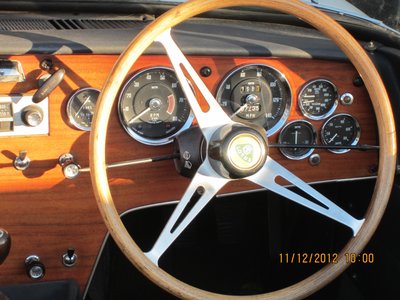
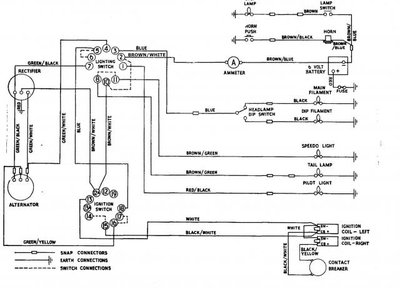
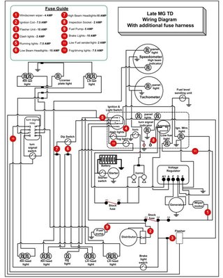
Thank you all for your input. I will take your wealth of information and read it carefully and work it out on my end.. Meg what a great area to put the gauges. Never thought of that area and they fit !! Also thanks for the wiring diagrams they will definitely help me... ..I did not want to drill into the dash and who needs a radio in the Elan not me!!
Happy motoring!!
Best regards to all,
Lou
Happy motoring!!
Best regards to all,
Lou
Louis Lottner
Elan S2 1965 #26-4840
Colin Chapman’s immortal words ‘Simplify, then add lightness’
Elan S2 1965 #26-4840
Colin Chapman’s immortal words ‘Simplify, then add lightness’
-

loueelotus - Second Gear

- Posts: 138
- Joined: 27 Mar 2010
Quart Meg Miles wrote:The S2 used a +ve earth dynamo so a 30-0-30 Amp meter would be better. I fitted mine (in the dash) in the early 70s by fitting a high current mating pair of Lucar connectors to the ammeter's wires (male to -ve terminal, female to +ve) then threaded them through a new grommet in the "firewall" near the solenoid. I unplugged the brown wire Lucar from the solenoid and plugged it into the ammeter's male and plugged the ammeter's female onto the solenoid. Easy, though work out the wire lengths before crimping on the Lucars.
To return to standard simply unplug and refit the brown wire back on the solenoid.
I like what you did to work it and it can be returned to the original state easily .. Can you please send me a drawing of what you did .. I find it difficult to understand exactly d=how you did it ..Much appreciated if you could do this for me..
Best Regards,
Lou
Louis Lottner
Elan S2 1965 #26-4840
Colin Chapman’s immortal words ‘Simplify, then add lightness’
Elan S2 1965 #26-4840
Colin Chapman’s immortal words ‘Simplify, then add lightness’
-

loueelotus - Second Gear

- Posts: 138
- Joined: 27 Mar 2010
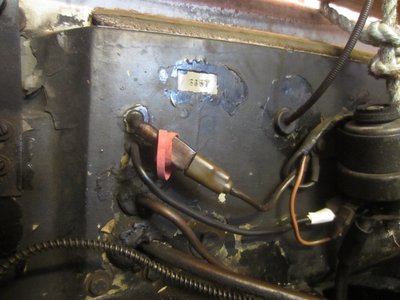
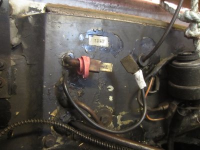
It was easy to take a few photos and just two will do. I've marked the Ammeter cables with red (-) and white (+) markers, but not the original brown cable, and posted the finished mod first so you can see where the connection is on the Starter Switch and how simple it is. I think the LH drive model still has the the Switch on the RH side so you may need longer wires to your ammeter and you can choose which side of the body to pass them through the bulkhead, but putting them where I did lets the original brown cable lie nicely and keeps the bulkhead above the engine clearer, the ammeter wires being behind the dash.
I notice that I used a seperate hole and grommet for each cable and threaded the cable through the grommet before fitting the engine bay connectors.
Provided crimps or nuts are tight and insulation sufficient there is no worry about short circuits. It's only loose wires and connectors which cause problems. I did have the sidelamp wire melt behind the dashboard once and it was due to my own dodgy wiring near the headlamps!
Meg
26/4088 1965 S1½ Old and scruffy but in perfect working order; the car too.
________________Put your money where your mouse is, click on "Support LotusElan.net" below.
26/4088 1965 S1½ Old and scruffy but in perfect working order; the car too.
________________Put your money where your mouse is, click on "Support LotusElan.net" below.
-

Quart Meg Miles - Coveted Fifth Gear

- Posts: 1170
- Joined: 03 Oct 2012
Trying to describe simply:
There is a thickish brown wire that goes from the live terminal of the starter solenoid, along the back edge of the engine compartment to the A terminal of a dynamo control box (or equivalent terminal block if you have an alternator). This carries the current that you want to measure.
Quart Meg inserted the ammeter into this wire, by taking a pair of wires through the firewall into the cabin, behind the dashboard to the two terminals of the ammeter. then at the wire ends in the engine compartment he put a female connector on one and a male connector on the other of the pair.
Then he pulled the brown wire off the solenoid spade connector and pushed the male wire end (from the ammeter) into it and then pushed the female ended wire (from the ammeter) onto the vacated spade connector on the solenoid.
He took care to get the polarity of the connections on the ammeter correct, see his description. But if you find that the ammeter goes the wrong way (eg showing charging when you turn headlights on with engine stopped) you have to reverse the connections on the ammeter.
Bill Williams
36/6725 S3 Coupe OGU108E Yellow over Black.
36/6725 S3 Coupe OGU108E Yellow over Black.
- billwill
- Coveted Fifth Gear

- Posts: 4417
- Joined: 19 Apr 2008
32 posts
• Page 2 of 3 • 1, 2, 3
Total Online:
Users browsing this forum: Andy8421 and 11 guests

