nippondenso alternator
17 posts
• Page 1 of 2 • 1, 2
I did some research. The connections under discussion are for the "regulator supply".
The "IG" terminal can go to a SWITCHED (IGN) +12V supply. The "L" terminal controls the charge lamp. When the alternator fails to produce power, this terminal is grounded. SO +12 V is not to be connected directly. The +12 goes to the indicator lamp and then to the "L" terminal.
An alternate method of wiring is to run switched +12 to the indicator lamp then to both "IG" and "L" terminals.
Bob
- rdssdi
- Fourth Gear

- Posts: 965
- Joined: 30 Sep 2003
I hope you don't mind if I broaden the question a bit. I'm interested in a Nippondenso alternator and would be interested in knowing the correct part/model number or application (year, make, model vehicle it was fitted to).
Slightly less important, but interested in your comments regarding ease of fabricating the bracketry.
Cheers,
Mark
Slightly less important, but interested in your comments regarding ease of fabricating the bracketry.
Cheers,
Mark
- straightcut
- New-tral
- Posts: 9
- Joined: 09 Jan 2004
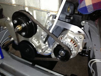
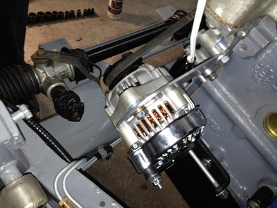
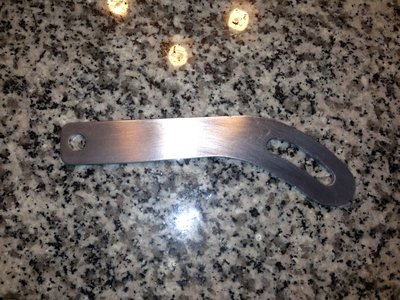
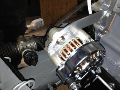
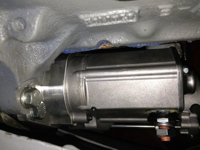
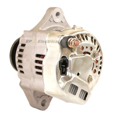
I just did the conversion with a 40 amp Kubota denso alternator which I believe is more than sufficient. As for vehicle model and year, these alternators are for a Kubota Tractor. Here is a link http://www.ebay.com/itm/281084675865?ss ... 3092wt_714 Just make sure you get the 3 wire one, one heavy wire positive to the starter, and the two wire plug for the ignition and alternator warning light. They are available from a number of suppliers on ebay for about $75. The brackets was easy using the original Lucas generator bracket on the bottom and fabricated bracket on the top. I had installed a DB water pump cartridge so my pulley alignment had to be spaced out a bit to match the pump and spaced out crankshaft pulley, so I just used some washers to space the alternator forward a bit. The top bracket was fabricated from a piece of aluminum. Just takes a bit of fitting and fabricating, but not difficult. I also fitted a gear reduction starter with a built in soleniod, so trying to figure out if I can still wire the alternator to the remote soleniod on the firewall so I can still use the remote starter button. Good luck with the project, Allan
Last edited by gearbox on Sun Feb 02, 2014 4:31 am, edited 1 time in total.
- gearbox
- Third Gear

- Posts: 388
- Joined: 12 Mar 2012
Gearbox:
Nice job on the bracket and install! I used a distributor plug wire boot over the big bolt to protect it from grounding on anything nearby, including tools in my hand.
Nice job on the bracket and install! I used a distributor plug wire boot over the big bolt to protect it from grounding on anything nearby, including tools in my hand.
There is no cure for Lotus, only treatment.
-

StressCraxx - Coveted Fifth Gear

- Posts: 1283
- Joined: 26 Sep 2003
StressCraxx wrote:Gearbox:
Nice job on the bracket and install! I used a distributor plug wire boot over the big bolt to protect it from grounding on anything nearby, including tools in my hand.
Thanks, I figure if I was going through all the trouble of restoring everything I was going to make it as bullet proof as possible. And yes, I have been looking for a rubber boot for the starter as it is deadly close to the frame, and one for the alternator, but surprised that no one has these. I check all the local parts stores and they tell me that no one had ever asked for one. I'll figure something out, but the starter has a plastic ring to seal some sort of rubber boot, so I assume it's out there somewhere. But a coil boot may work as well. Thanks again Allan
- gearbox
- Third Gear

- Posts: 388
- Joined: 12 Mar 2012
Allan,
Nice job of the alternator install.
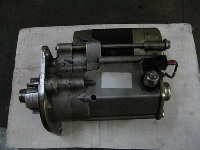
Re the starter. Yes you can keep the remote solenoid you just need to link the starter power terminal to the spade terminal. As pic shows. You guys in the states seem to use the opposite hand gear reduction starters to us in the UK so for me the power terminal ends up next to the sump. But if you still use the remote solenoid it's only live during cranking, I don't see that as a problem.
Cheers
John
- elanman999
- Fourth Gear

- Posts: 500
- Joined: 12 Nov 2005
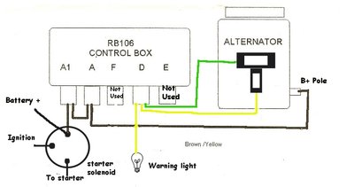
Thanks John, saved me lots of researching. So if I understand correctly, the OEM solenoid is energized and sends a current to the starter motor and since the starter soleniod is connected to the motor, it engages both the starter solenoid and motor at the same time. Simple, thanks. So to completely to answer this topic and to be painstakingly clear, we have three wires from the alternator, and in my case a Kubota Denso. The big pole wire should be at least 8 ga. for a 40amp (maybe 4 ga. for higher amps), and is connected to the "A" terminal on the regulator control box, which in turn is connected to the battery side of the oem soleniod. Then you have two wires that should have a "T" formation plug.
As you can see from the above pics, the horizontal spade is associated with the green wire, and the vertical spade connects with the yellow on the plug. To confuse this some more, I have seen this same connector with yellow and red and red and black. But going with our horizontal and vertical orientation, the horizontal spade is for the "exciter" which is connected to the control box which has a 12v current when the ignition is switched on. The vertical spade is for the alternator warning light in the dash. But from what I understand these two wires are tied together and joined at the voltage regulator box at the "D" terminal, which I assume is a 12v source when when the ignition is switched on. With the ignition switched on, it supplies a 12v current, but when the alternator is not being rotated, the yellow wire is supplying a ground signal, which in turn lights the warning light. When the alternator starts turning, it puts a 12v signal to the yellow wire and then defeats the warning light and turns it off. We eliminate terminals E which is the ground and terminal "F" which was the wire from the old Dynamo. Not sure if it would matter if "E" was eliminated or left in place, but effectively it would defeat the control box completely thus turning it into a simple terminal box. Let me know if I got this right. Thanks Allan
As you can see from the above pics, the horizontal spade is associated with the green wire, and the vertical spade connects with the yellow on the plug. To confuse this some more, I have seen this same connector with yellow and red and red and black. But going with our horizontal and vertical orientation, the horizontal spade is for the "exciter" which is connected to the control box which has a 12v current when the ignition is switched on. The vertical spade is for the alternator warning light in the dash. But from what I understand these two wires are tied together and joined at the voltage regulator box at the "D" terminal, which I assume is a 12v source when when the ignition is switched on. With the ignition switched on, it supplies a 12v current, but when the alternator is not being rotated, the yellow wire is supplying a ground signal, which in turn lights the warning light. When the alternator starts turning, it puts a 12v signal to the yellow wire and then defeats the warning light and turns it off. We eliminate terminals E which is the ground and terminal "F" which was the wire from the old Dynamo. Not sure if it would matter if "E" was eliminated or left in place, but effectively it would defeat the control box completely thus turning it into a simple terminal box. Let me know if I got this right. Thanks Allan
- gearbox
- Third Gear

- Posts: 388
- Joined: 12 Mar 2012
Hello everybody
Yesterday I check the battery output current. Engine off and ignition key on AUX position.
I read a 3.5 A current which seems to be a lot.
After investigation, I find this current go into the IGN line of the alternator.
My alternator is a 40 A denso.
What is your experience ?
Yesterday I check the battery output current. Engine off and ignition key on AUX position.
I read a 3.5 A current which seems to be a lot.
After investigation, I find this current go into the IGN line of the alternator.
My alternator is a 40 A denso.
What is your experience ?
Elan Plus 2 S130/5 1974
-

Olympicblue - First Gear

- Posts: 25
- Joined: 22 May 2013
Battery amperage is independent of which alternator you are using while the motor is not running or how its wired. Most batteries are rated at 70 amp hours and 3.5 Amps, so your reading of 3.5 Amps is normal which means it should be able to supply a 3.5 Amp draw for 20 hours (70/3.5 = 20). Hope this helps. Thanks Allan
- gearbox
- Third Gear

- Posts: 388
- Joined: 12 Mar 2012
rgh0 wrote:Sounds like a faulty alternator diode
cheers
Rohan
Hi Rohan,
Thank you,
If it is, Nippondenso is falling in my esteem !
Is there a simple method to confirm ?
Damien
Elan Plus 2 S130/5 1974
-

Olympicblue - First Gear

- Posts: 25
- Joined: 22 May 2013
Olympicblue wrote:rgh0 wrote:Sounds like a faulty alternator diode
cheers
Rohan
Hi Rohan,
Thank you,
If it is, Nippondenso is falling in my esteem !
Is there a simple method to confirm ?
Damien
Hi Damien,
jumping in - you may take it apart and check the 6 diodes with a multimeter... or you may take it to Bonneuil Electrique 79 av de Paris on the N19, they have a test bench where they would typically test your unit for free (then offer you to buy a new one - no affiliation on my part).
S4SE 36/8198
-

nmauduit - Coveted Fifth Gear

- Posts: 2002
- Joined: 02 Sep 2013
17 posts
• Page 1 of 2 • 1, 2
Total Online:
Users browsing this forum: No registered users and 29 guests


