headlamps
18 posts
• Page 1 of 2 • 1, 2
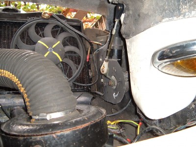
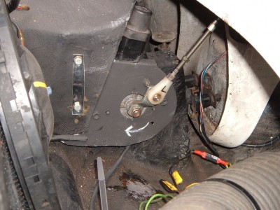
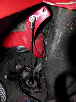
Thanks for the pic's of the mounts John. Very helpful here. Hope to get my pod motors installed early in the new year.
Raygray, I have looked into the electric pods quite extensively. A couple of points...
The archives show several installations, so worth a search.
The wiring of the motors can be a bit confusing, but once you get the idea not too bad. Can provide more detail when you need it.
The motors generally come from various Japanese cars. Mine are from an 80's vintage Toyota Celica, and look similar to John's. The motors themselves are common across several makes, including Supra, Celica, Mazda Miata, etc. The wire colours vary, but the motors are similar. Just from visuals on the 'net, the motors in Porsche a 924, Triumph TR7, etc. look pretty similar as well. Anyway, don't worry too much about the specific wire colours quoted in any posts or Internet searches; just need to figure each colour out on yours with a multi-meter.
The motors require a relay to control them. Relay is dual acting, one terminal has a normally closed circuit and another terminal has a normally open circuit. Can provide a wiring diagram in the new year if needed. The stock control relays for various donor cars can be a bit daunting; I will just use a generic one for this function.
In my set-up, the pod motor control is taken from the headlight micro-switches. These set-ups on the Loti vary between Federal and non-Federal, Elan, & Plus 2, etc., so you will have to look at this carefully first. In my Federal (Fail-Safe) Plus 2 set-up, the two micro-switches have normally closed and normally open contacts, both of which are required to correctly control the pod motors. Becomes pretty clear with a wiring diagram, but check your set-up has this functionality.
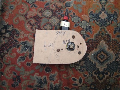
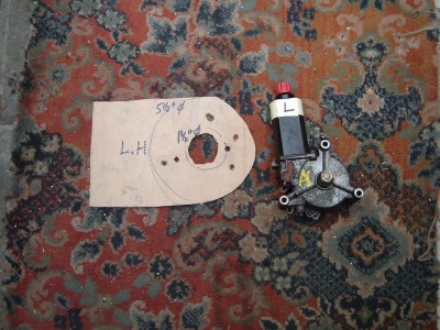
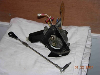
The red knob on the top of John's motor allows you to manually move the pod, so no sweat if you have a fuse or circuit failure; won't be stuck without lights. However, one will want to mount where you can get at the knob easily, which looks very good in John's install.
Mine will use only one motor as both pods are mechanically connected on a rod; I believe the Elan and non-Federal Plus 2's are generally a bit different and would require two motors, so check your application before heading to the wrecker to get the motors. Also remember to take both sides of the motor electrical plug from the donor car when you remove the motors for a clean install.
From previous posts, can be a bit of a deal to get the rod lengths adjusted. Have not done this part, but you can see how John finessed it. Possible source for different rod lengths and fittings was suggested on previous posts; control arms used in model aircraft apparently work well so hobby shop was suggested. Advice is to only move motors manually during set-up; motors would be absolutely powerful enough to do serious damage to the fibreglass if miss-adjusted during fitment! Motors are VERY powerful, so be careful when testing them out. They could definitely break a finger if you tried to stop them!
The pod motors have a rotary switch built in to control starting and stopping the motor in the correct position. This requires the motor to be grounded out to stop it. Without the ground connection from the control relay correctly wired, the motor will continue to rotate and pods will cycle up and down continuously. Very clear with the wiring diagram, but not so obvious when trying to figure it out. I thought the motor was pouched until I figured this out
Mine are tested out for wiring, but not installed yet.
Merry Christmas to you as well.
Last edited by stugilmour on Fri Dec 25, 2009 9:52 pm, edited 1 time in total.
Stu
1969 Plus 2 Federal LHD
1969 Plus 2 Federal LHD
-

stugilmour - Coveted Fifth Gear

- Posts: 1951
- Joined: 03 Sep 2007
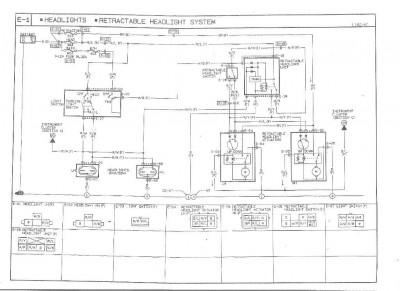
Yes John, that is one of the diagrams I used to figure it out as well. IIRC, that one is the Miata?
I dispensed with the "timer relay" and the "passing switch" feature shown in the attached. Never did quite figure that part out, but my guess was the timer somehow told the pods to retract after using "flash to pass" on the column stock. This feature is not required on my Plus 2, as the stock column switch does not have this feature.
If anyone is interested, the column switch can be replaced with a similar one from a Mk 2 Spitfire I believe, which has a secondary switch incorporated (pull dimmer stock toward steering wheel to activate/close a momentary switch). I have modified one I got on eBay so it will provide "flash to pass", but I am connecting it to a driving lamp relay instead of the headlamp relay to avoid having to figure out the required control to raise the pods momentarily and have them revert to closed after a few seconds. This feature requires a minor modification of the Triumph switch to work, and the addition of a "hot at all times, fused (purple)" supply to the column switch so the "flash to pass" can be activated with the headlamps in the off position. In stock configuration the column switch for the headlamps is essentially supplied from the dash light switch only.
Some of the stuff shown in the diagram is part of the motor unit itself. However, the relay portion is required to control the pods.
I found all of it a bit confusing at first, but the final sketch diagram I did up is considerably simpler to read. Will see if I can clean it up a bit and post after the holidays. All fairly easy with the dash and motors sitting out of the car in a warm basement!
Back to Christmas cheer!
Stu
1969 Plus 2 Federal LHD
1969 Plus 2 Federal LHD
-

stugilmour - Coveted Fifth Gear

- Posts: 1951
- Joined: 03 Sep 2007
raygray wrote:Happy xmas everyone.
Has anybody converted the pop up headlamps to electric operation.
Last edited by elansprint71 on Fri Oct 22, 2010 7:29 pm, edited 1 time in total.
Cheers,
Pete.
http://www.petetaylor.org.uk
LOTUS ELAN flickr GROUP: https://www.flickr.com/groups/2515899@N20
flickr: http://www.flickr.com/photos/16096573@N02/sets/72157624226380576/
https://www.flickr.com/photos/16096573@N02/
Pete.
http://www.petetaylor.org.uk
LOTUS ELAN flickr GROUP: https://www.flickr.com/groups/2515899@N20
flickr: http://www.flickr.com/photos/16096573@N02/sets/72157624226380576/
https://www.flickr.com/photos/16096573@N02/
-

elansprint71 - Coveted Fifth Gear

- Posts: 2624
- Joined: 16 Sep 2003
raygray wrote:Has anybody converted the pop up headlamps to electric operation.
As you can see, many of us have done the conversion.
The ubiquitous motors are all from the same Japanese maker that help make-up different installations. Mine came from an early MX5 with the installation bracket that suited the Elan. The motors have five (5) electrical connections that are easy to understand.
I can eMail you with more information, if you wish.
Brian Clarke
(1972 Sprint 5 EFI)
Growing old is mandatory..........Growing up is optional
(1972 Sprint 5 EFI)
Growing old is mandatory..........Growing up is optional
-

bcmc33 - Coveted Fifth Gear

- Posts: 1708
- Joined: 10 Apr 2006
Nice mount Brian. Wish there was a MX5 Miata at the wrecking yard when I went for my pod motors  . For my donor car, I think the motors were mounted directly to the unibody, so I took just the motors and wire plug.
Kind of interesting comparing your photos to John's. Looks like your motor arm in the full down position is clocked differently than John's. Wondering if you guys had to clock the actuation arm on it's shaft, or just adjusted your mounts to suit? The nut on my arm is VERY firm, so not sure if the arm is keyed on to the shaft, and don't want to needlessly break it.
Here is my attempt at the "simplified" wiring diagram. It is a PowerPoint 97 file. Trying to make sketches of my wiring efforts for future use.
Stu
1969 Plus 2 Federal LHD
1969 Plus 2 Federal LHD
-

stugilmour - Coveted Fifth Gear

- Posts: 1951
- Joined: 03 Sep 2007
The arm is attached to the motor spindle by a tapered spline. So you can place the arm approximately in the position you want and make fine adjustments via the plastic knob on the top of the motor.
Below is the circuit I used - kindly donated by Ian Phillips.
Below is the circuit I used - kindly donated by Ian Phillips.
Brian Clarke
(1972 Sprint 5 EFI)
Growing old is mandatory..........Growing up is optional
(1972 Sprint 5 EFI)
Growing old is mandatory..........Growing up is optional
-

bcmc33 - Coveted Fifth Gear

- Posts: 1708
- Joined: 10 Apr 2006
Brian, Forgive me jumping in here. I've been thinking about doing the conversion on my car for some time. Your conversion looks very neat, do you mind if I ask a couple of questions which hopefully may be helpful to others too?
Are the brackets as shown in your pictures the unmodified MX5 brackets?
Are the operating rods modified or did you just have to work out a suitable pivot point on the pods?
I assume the relays shown on the excellent wiring diagram are a standard type?
One thing which has made me a bit reluctant to do the conversion is the fear of putting too much strain on the pod pivot points and causing cracking. That said, I'm fed up with droopy old vacuum operate lights. Everything is new but they are never firmly erect (if you know what I mean )
)
Any advice gratefully received
Are the brackets as shown in your pictures the unmodified MX5 brackets?
Are the operating rods modified or did you just have to work out a suitable pivot point on the pods?
I assume the relays shown on the excellent wiring diagram are a standard type?
One thing which has made me a bit reluctant to do the conversion is the fear of putting too much strain on the pod pivot points and causing cracking. That said, I'm fed up with droopy old vacuum operate lights. Everything is new but they are never firmly erect (if you know what I mean
Any advice gratefully received
John
No longer active on here, I value my privacy.
No longer active on here, I value my privacy.
-

nebogipfel - Coveted Fifth Gear

- Posts: 1274
- Joined: 25 Sep 2003
Hi
There have been a few postings on this over the years, have a look at;
elan-f15/electric-light-pods-t17041.html
Jason
There have been a few postings on this over the years, have a look at;
elan-f15/electric-light-pods-t17041.html
Jason
50/0951 1968 Wedgewood blue +2, 1990 Mini Cooper RSP
-

Jason1 - Coveted Fifth Gear

- Posts: 1346
- Joined: 03 Nov 2005
That is an interesting thread Jason.
The problem John was reporting in this thread is the same problem I had, where the pod motor would continue to spin under no load and not stop at the 180 degree positions where the rotary switch cut-outs are located. As mentioned above, I have not tried them under load yet.
I googled up pod motors, and found a rather lengthy post by a Porsche 924 owner that explained the logic behind the motors; took several readings to get it. The "trick" to prevent constant cycling of the motors is to ground the motor feed as soon as the rotary switch reaches the up or down fixed position. This causes the motor to freeze by induction or some such, much like the "brake" circuit on a slot car grounding out the drive motor or applying reverse voltage. This also prevents the motors from moving again without current being applied from the next input signal in the cycle.
This configuration therefore prevents the problem Ian mentioned in his diagram - twisting the red manual movement knob forward with the power connected will cause the pod to travel through one cycle. With the motor grounded, it will not end up being activated; sort of hard to explain but it works. If you turn the knob in reverse disrection, it will simply cycle forward to it's former resting position as soon as the wiper makes contact. This is how they make it safe to be powered in hot at all times, fused rather than only with ignition on.
I notice some of the wiring configurations use one pod control relay for two independent motors. I don't think this will work with the grounding configuration I am using, as if the motors are slightly out of sync with one another, both motors will stop when the first pod reaches it's final position.
My previous ppt slides show what I am using for a Federal Plus 2. I understand for other models, the headlight micro-switch is single acting only, and does not have the NC terminal provided in the Federal version. In this case one would need an additional relay to provide a NC terminal. I have added a slide to the ppt version below that shows this.
Note my slides only show one motor and motor control relay because the pods are attached mechanically in my car. For the separate pod style, just add one more motor and motor control relay with the same configuration.
I have also added a couple of slides that show the operation of the rotary switch in three positions, fully down, fully up, and while moving. My earlier post may have been confusing as it showed one of the rotary switch wipers out of position; they are all in a single line inside the switch body. This was the most difficult part to get from the various schematic diagrams because the rotary switch is often shown as a NC or NO switch, which is sort of only relevent in one resting position, typically with the pod down I believe.
I looked over Brian's diagram from Ian, but I am afraid I can't fully figure it out. It is possible that the pod motors are slightly different between donor car models, which may account for some of my confusion. I do notice it shows the diodes in the reverse position to mine, and two of the relays seem to be wired differently, so not sure how it works.
Regarding the question on what type of relays are being used, all of the various configurations appear to use a "Five Blade Changeover". One of the pages in the ppt file below has the link to where I bought mine, but these are a very standard configuration made by several manufacturers. The link has good drawings of the various types available, and most manufacturers print the diagram on the top of the relay case, so pretty easy to find.
Anyway, here my "enhanced simple" diagram. Thanks to all again for the excellent posts showing the variety of mounts and the ability to clock the motor arm, as this is very helpful to me.
Stu
1969 Plus 2 Federal LHD
1969 Plus 2 Federal LHD
-

stugilmour - Coveted Fifth Gear

- Posts: 1951
- Joined: 03 Sep 2007
Eric, Whenever someone mentions stripping parts of the car to save weight I'm always tempted to ask how much the driver weighs? 

John
No longer active on here, I value my privacy.
No longer active on here, I value my privacy.
-

nebogipfel - Coveted Fifth Gear

- Posts: 1274
- Joined: 25 Sep 2003
18 posts
• Page 1 of 2 • 1, 2
Total Online:
Users browsing this forum: No registered users and 12 guests

