S2 Elan door surround Latice - is yours rotten too
30 posts
• Page 1 of 2 • 1, 2
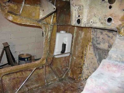
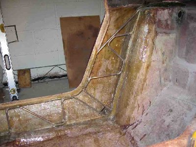
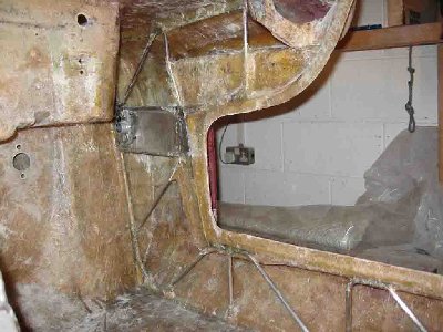
I picked up Andys S2 Elan body today to replace the rotten lattice work that surrounds the doors on each side. The damage is typical of what I have seen in the past of the early S2's, the later latice work was galvanized and hold up much better. Here are some of the before photos.
The left side was worse that the right but both need to be cut out and replaced. The left side was vacuumed and any loose or broken fiberglass was removed too get at the iron oxide. The right side was just vacuumed and fiberglass will need to be cut out as the rusted lower portion of the truss hasn't rotted to the point of breaking up the fiberglass I hope to get some work done on it in the next couple days and I'll post some pictures as I go.
Gary
-

garyeanderson - Coveted Fifth Gear

- Posts: 2626
- Joined: 12 Sep 2003
Hi
Like yours mine rotted on one side. I never replaced the steel latticework- instead I simply removed all the rotted parts (ie most of the lattice) and every 6 inches along the sill length fibreglassed in some one inch thick grp columns linking the floor to the upper part of the sill. Much stronger than the original idea- in fact at one point I contemplated simmply making the sill fully enclosed with a grp wall along its length.
Anyway I fitted these "columns" some 20 years ago and have forgotten them- no creaking/movement when the car is jacked along the sill either!
John
- worzel
- Fourth Gear

- Posts: 611
- Joined: 13 Jan 2004
Hi John
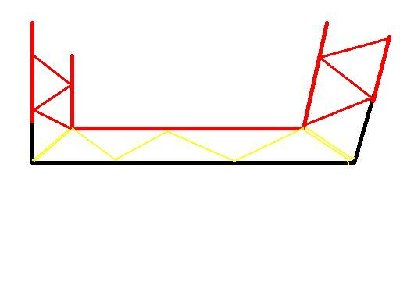
Interesting idea, I have thought along those lines of just replacing the whole steel structure with a fiberglass panel and bonding it in before. I just never did it. The rotted area of Andy's Sills will be cut out (the lower longeron and the diagonal bracing) and replaced with 3/8 inch for the longeron and ? inch for the diagonal Bits. I drew a diagram in MS paint, Orange is the original lattice that remains, the black and yellow will be completly cut out and replaced. The black 3/8" piece will be bent to fit and the fit checked until it fits correctly and then mig welded in at both ends. A 2 1/2 gallon water based fire extinguisher is at hand for all welding operations and a garden hose at the ready too. I then need to make a jig to bend up the 1/4 inch portion in yellow, using an oxy-aceteline torch to heat and bend to the correct shape. Starting at one end, it is mig welded to the old and new longerons along the length of the sill. a 7/16 x 20 unf nut is welded in at the rear for the lap belts. when all of the welding is complete, two layers of 1 1/2 oz mat will bond it back to the original fiberglass on the inside. The bottom of the Elan will get two layers also, these are approximately 2 inch wide strips that will bond the outer sill back to the original floor. The original lattice lasted a good long time, the car was used for a daily driver through several years of New England weather including 3 or 4 winters. I don't see this repair failing again in my lifetime as it won't see that kind of use again.
I have added some more photos of the lattice after I cut away the strips of glass retaining them so that I can get some measurements. There was a lot of iron oxide that was removed with the help of a flat blade screwdriver and a small mallet. Once I get the lattice cut out entirly I will grind back the fiberglass on each side of the lower longeron a couple inches to prep it for the new glass to be layed up after the latice is welded back together. At the moment the whole left hand sill has no attachment to the floor area, the right hand side is much better in that respect and is only delaminated the front 8 or so inches.
Gary
- Attachments
Last edited by garyeanderson on Sun Jul 22, 2007 4:04 pm, edited 1 time in total.
-

garyeanderson - Coveted Fifth Gear

- Posts: 2626
- Joined: 12 Sep 2003
Hi Gary,
I am rebuilding one now as we speak, well started a year or so back and am trying to finish. Like you too many projects. I bought all the same diameter rod in staianless steel and have bent up a new one from stainless and have been grinding out the glass to remove the old and replace with the stainless assembly. Should hold up to the moisture much better. This car had sat outside for many years in storage with a leaking cover when I bought it.
I like the glass col idea as the grinding is a real pain!
Your photos look very familiar! Good luck.
Mark
-

memini55 - Third Gear

- Posts: 345
- Joined: 09 Jan 2004
I will be following this topic with great interest, since it's my car! This approach seems like a good alternative to replacing the entire lattice, since only the bottom few inches are rotted out. Using steel also allows Gary to put in new outer seat belt mounts.
Here are some photos of Gary (assisted by Beauregard) maneuvering the body into his pickup and heading out. He has this operation down to a science.
Here are some photos of Gary (assisted by Beauregard) maneuvering the body into his pickup and heading out. He has this operation down to a science.
- Attachments
Andrew Bodge
'66 Elan S2 26/4869
I love the sound of a torque wrench in the morning. Sounds like... progress.
'66 Elan S2 26/4869
I love the sound of a torque wrench in the morning. Sounds like... progress.
-

RotoFlexible - Fourth Gear

- Posts: 624
- Joined: 01 Sep 2005
I picked up steel this morning and I got enough for two sets for both sides, that is unless I screwed up on the new bending jig I made when I got home. Hopefully I'll try it out tomorrow and find out.
-

garyeanderson - Coveted Fifth Gear

- Posts: 2626
- Joined: 12 Sep 2003
I went out to see my friend Carl today, Carls been repairing, rebuilding cars for 45 years. Well I needed to use the oxy/acetelene torches for the jig and we had lunch and then went to work. The results are the raw products, tomorrow I get to see if they even fit or if I need to try it again with the second pair that I bought as an extra set.
-

garyeanderson - Coveted Fifth Gear

- Posts: 2626
- Joined: 12 Sep 2003
Well the weather is suposed to be hot and humid, 90's tomorrow so I thought I better get my a$$ in gear and get on with the missery. I got the wiz wheel out and cut out both sides. the Left side is a lot worse than any I have done in the past, I had to cut the lower longeron at the top of the Elan only about 2 inches from the top of the body, it was packed with mud and rust. The 3/8 inch rod was rotted down to less than a 1/4 inch in spots. Lots of grinding of fiberglass and contact cement, its nearly ready to fit the new pieces of steel that I bent up yesterday and weld them in.
-

garyeanderson - Coveted Fifth Gear

- Posts: 2626
- Joined: 12 Sep 2003
Steve,
Nice looking finished project! Looks like you built up your own framework. Is it galvanized or stainless or mild steel?
So now that you are done how many hours to do both sides? And further your comment "do it my way" perks the question of your meaning on that comment?
This site is so helpful to get everyones input on repairs!
Mark
-

memini55 - Third Gear

- Posts: 345
- Joined: 09 Jan 2004
Hi Mark
The frame work is in stainless tube which came in 3m (10ft) lengths which I wire locked together and then had welded.
I have no idea how long it to all took but at the same time I reinforced the pedal box area and made the pedal box seat properly on both mounting points.
Changing the design meant it had to be more accurately constructed. The bracing a long the sill is made in one piece and using vertical supports compared to the standard angled, left no room for error. This is also FHC which obviously makes it difficult to get the frame in and out.
I changed the design to make pedal box mounting more rigid and to better clear the side bars of the roll cage but the design made it very difficult to fit the side bars and ended up slicing into the rear arch.
If you do this your self always mount the pedal box and make sure it?s square and can rotate freely before bonding. I took a lot of trouble over this and refurbished the box at the same time ? mine by the way had one of the bushes missing which depending how cynical you are may have been to ?help? with the alignment or just an assembly error.
If I was doing this again I would incorporated a circle in to the design by the lock area to house some speakers.
My original main bars were in places the same thickness as the cross bracing so think twice before jacking the car on the sill.
Cheers
Steve
- patrics
- Fourth Gear

- Posts: 537
- Joined: 21 Sep 2003
After around 6 hours of grinding on Friday and Saturday mornings (85 degrees and quite humid, wearing a Tee shirt and a hooded sweatshirt, theres nothing like it to make you sweat) and another 4 hours of glassing I finally got finished the rough fiberglass work on the boot floor, a few (?) more hours with some polyester putty and a couple more sanding I should be good in the boot. Today and got back to the job at hand and started welding in the steel I bent up last Tuesday.
- Attachments
-

garyeanderson - Coveted Fifth Gear

- Posts: 2626
- Joined: 12 Sep 2003
A very interesting thread and one which nobody seems to have addressed in so much detail. Thanks, Gary, Steve.
Gary, I think we discussed this subject in 2000 and I still haven't done the job yet. Too many other projects! Anyway, having welded up the new frame part, could it then be bonded in rather than welded. I am not keen on cutting access holes and welding that close to the glass, especially as I am a welding novice.
So, to bond or weld, that is the question?
Roy
'65S2
-

elj221c - Fourth Gear

- Posts: 539
- Joined: 12 Sep 2003
Hi Roy
Glad you have enjoyed the thread. I think that the latice replacements are avilable in the U.K. According to the buckland book, I saw some of the later S3/S4 latice units but I'm not sure that the S1 and S2 versions are available . Anyway, you have to work with what you have and I didn't want to cut the whole unit out and make a complete replacement section. This would entail making sure that the pedal mounts end up in pretty much the same position and the wiper mount also. As it is the jig I made was not an exact fit, most of the points/intersections lined up nicely but a couple had to be moved slightly. I guess you might not need the access ports if you are an experianced welder but I am not one of those people. In any event, no one will know that they were there after a coat of semi gloss black paint is applied over them as they will be covered on the inside with a couple layers of 1 1/2 ounce chopped stand matt. If I would have had the complete latice in hand I would have replaced the whole unit and cut out and bonded in one side at a time. As it is I did it the way I know how and that is to weld in the lower longeron first and then weld the bridging in to the upper and lower longerons from point to point as I went along.
Gary
-

garyeanderson - Coveted Fifth Gear

- Posts: 2626
- Joined: 12 Sep 2003
30 posts
• Page 1 of 2 • 1, 2
Total Online:
Users browsing this forum: No registered users and 24 guests


